
Views: 0 Author: Site Editor Publish Time: 2026-01-21 Origin: Site
A reciprocating compressor converts mechanical rotation into repeated linear piston movement to compress gas inside a cylinder. If you are trying to understand how does a reciprocating compressor work, the key is to follow two processes at the same time: the transmission of mechanical force through the crankshaft and connecting mechanism, and the change in gas volume and pressure inside the cylinder. Each component has a specific role, but the compressor only functions effectively when the entire mechanical and gas-flow system works as one coordinated unit.
Unlike dynamic compressors that continuously accelerate gas, a reciprocating compressor is a positive-displacement machine. A defined volume of gas enters the cylinder, becomes trapped, and is compressed as the piston reduces the available space. This operating principle makes reciprocating compressors particularly suitable for applications requiring controlled gas delivery and relatively high discharge pressures.
A reciprocating compressor is a positive-displacement compressor that uses a piston moving back and forth inside a cylinder to increase gas pressure. During the suction stroke, cylinder volume increases and gas enters through the suction valve. During the compression stroke, the piston reduces cylinder volume until internal pressure becomes high enough for the discharge valve to open.
Understanding how does a reciprocating compressor work therefore starts with the pressure-volume relationship inside the cylinder. As the enclosed gas volume decreases, gas pressure rises. Temperature normally rises during compression as well, which is why cooling becomes increasingly important in high-pressure and multistage compressor systems.
Industrial reciprocating compressors may use single-acting or double-acting cylinders, and compression may occur in one stage or across several stages. Their layouts can differ considerably, but the fundamental operating sequence remains the same: admit gas, reduce its volume, increase its pressure, and discharge it to the downstream system.
The working principle is based on positive displacement. Rather than producing pressure mainly through gas velocity, the machine physically changes the volume of a closed compression chamber. The piston creates this changing volume as it travels between the two ends of the cylinder.
When people ask how does a reciprocating compressor work, they often focus only on the piston. In reality, the piston cannot create controlled compression without the crankshaft, connecting rod, crosshead or piston-guiding arrangement, piston rod, cylinder, and automatic suction and discharge valves. Mechanical motion and gas-flow control must remain synchronized even though the valves are generally operated by pressure differences rather than by a mechanically timed valve train.
At the beginning of a compression cycle, the cylinder contains gas at approximately suction conditions. As the piston moves toward the cylinder head, the available space becomes progressively smaller. The gas is therefore compressed, causing pressure and temperature to rise until cylinder pressure exceeds the pressure acting on the discharge side.
This relationship explains the core physics behind how does a reciprocating compressor work. The piston does not directly "create pressure" as an isolated action; instead, it reduces the volume available to a confined gas. Pressure develops because the gas is forced into a smaller space while the cylinder and valves prevent uncontrolled escape.
In actual compressors, the process is more complex than an ideal pressure-volume relationship because heat transfer, valve losses, gas leakage, clearance volume, friction, and gas properties all influence performance. For SEO content aimed at technical buyers or maintenance personnel, these factors are more useful than simply stating that the piston "pushes gas."
Most reciprocating compressors are driven by a motor or another prime mover that delivers rotational torque. The crankshaft receives this rotational input and transfers it through the connecting rod. Crank geometry then converts rotary motion into the linear reciprocating movement required by the piston.
In larger crosshead-type machines, the connecting rod acts on the crosshead rather than directly on the piston. The crosshead travels along guides and transfers force through the piston rod, helping maintain controlled axial movement. This arrangement reduces the lateral loading that would otherwise act directly on the piston and cylinder surfaces.
This mechanical conversion is central to how does a reciprocating compressor work because pressure generation depends on accurately controlled piston displacement. Excessive clearance, poor alignment, worn bearings, or unstable guidance can affect more than mechanical reliability; they may also influence sealing, vibration, friction, and long-term compressor performance.
A reciprocating compressor should be viewed as an energy-transfer chain rather than a collection of separate parts. Mechanical energy enters through the drive system, is converted into reciprocating force, and is ultimately transferred to the gas in the form of increased pressure. The following components perform the main functions in that chain.
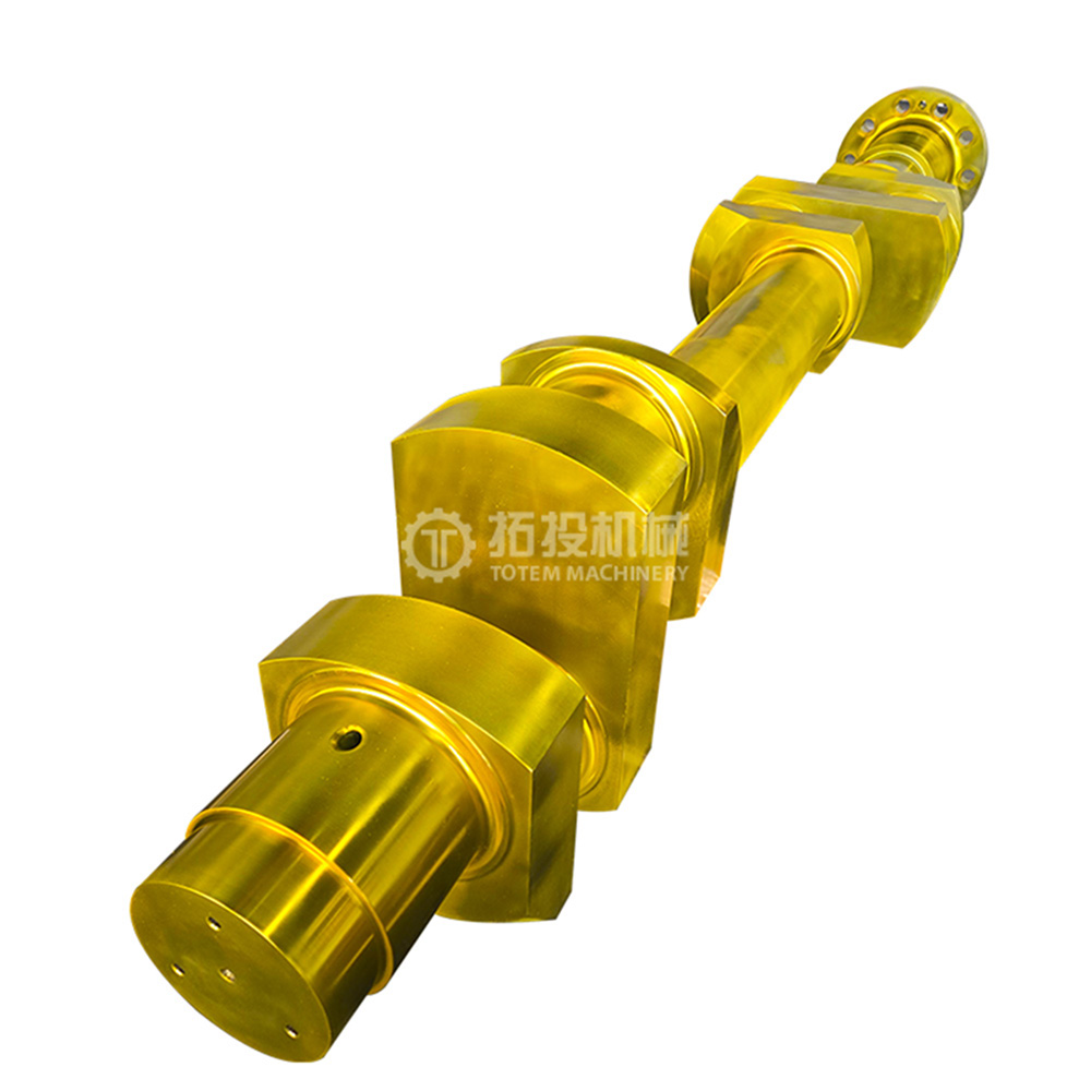
The crankshaft receives rotational torque from the drive system and provides the eccentric motion required to move the connecting rod. Because it experiences repeated cyclic loading, its geometry, bearing interfaces, alignment, and surface condition influence mechanical stability. A crankshaft problem can therefore affect vibration, bearing load, connecting-rod motion, and the accuracy of the piston stroke.
When explaining how does a reciprocating compressor work, the crankshaft is best described as the starting point of the compressor's mechanical motion-conversion system. It does not compress gas directly. Instead, it supplies the controlled motion that eventually drives the piston through the compression cycle.
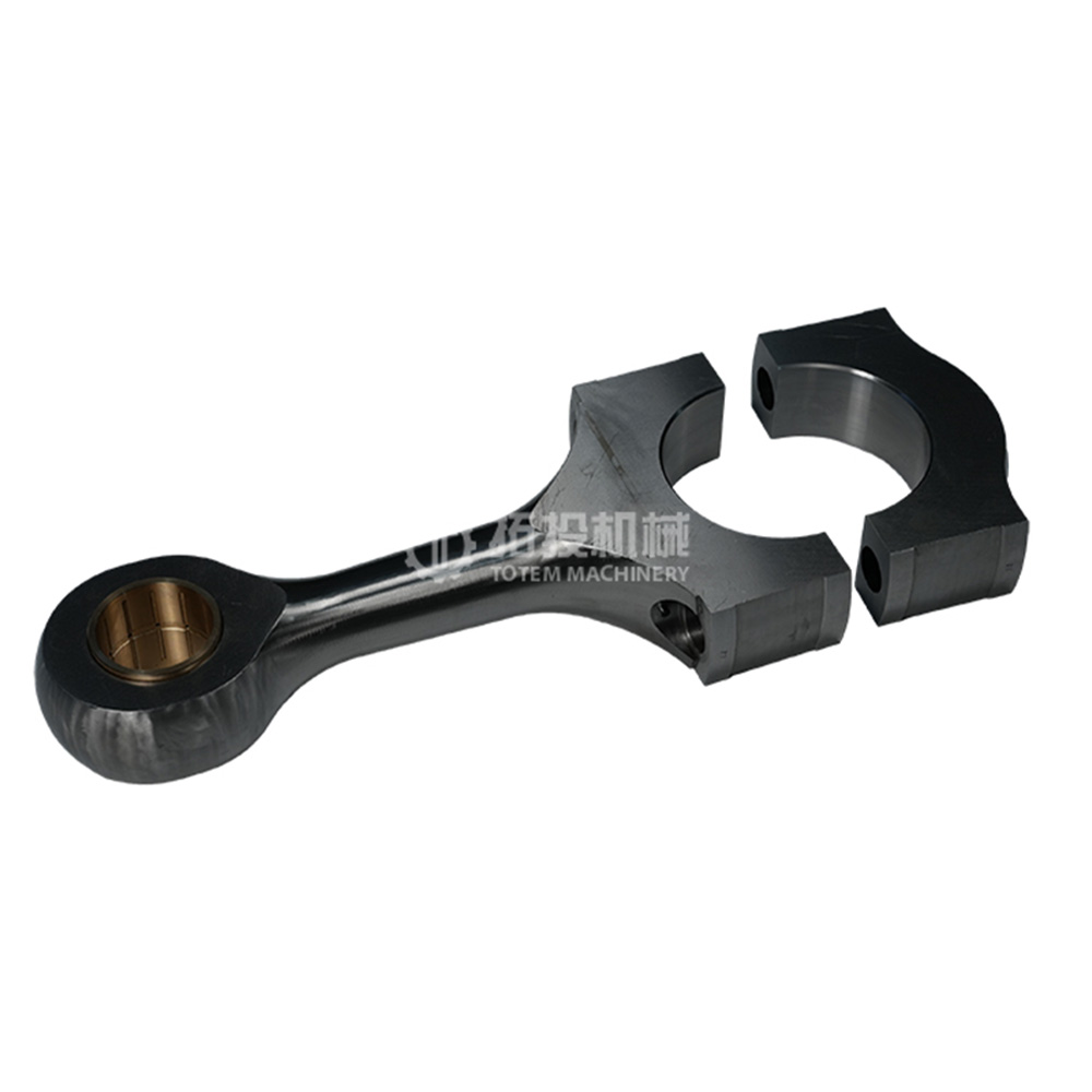
The connecting rod transmits force between the rotating crankshaft and the reciprocating assembly. Its motion changes continuously throughout each revolution, creating the forward and backward movement required for the piston stroke. Loads also reverse repeatedly, so the rod, pins, bearings, and mating surfaces must operate reliably under cyclic stress.
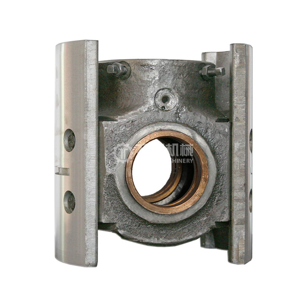
In a crosshead-type reciprocating compressor, the crosshead provides a guided linear interface between the connecting rod and piston rod. This helps separate the angular movement of the connecting rod from the straight-line movement required by the piston. For larger industrial machines, that guided motion is particularly valuable because it limits side thrust on the piston assembly and supports stable alignment.
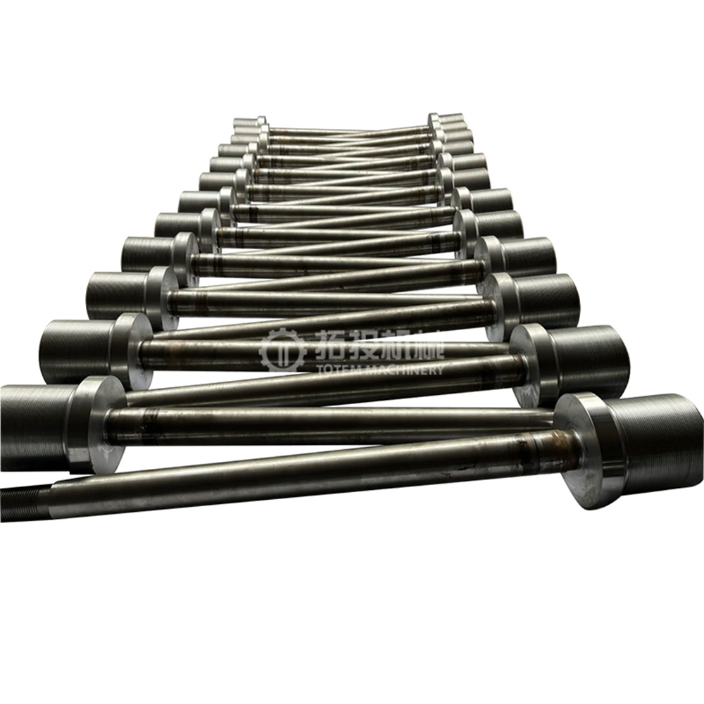
The piston rod connects the guided reciprocating mechanism to the piston. It repeatedly transmits compressive and tensile loads while passing through the cylinder-end sealing system. Alignment is therefore important because excessive deviation can accelerate wear in packing, guides, piston rings, or related components.
The piston is the component that directly changes the working volume of the cylinder. As it moves away from the cylinder head, space becomes available for incoming gas; as it moves toward the head, that space decreases and compression begins. This is the most visible part of how does a reciprocating compressor work, but the piston depends on every upstream component to maintain the correct stroke.
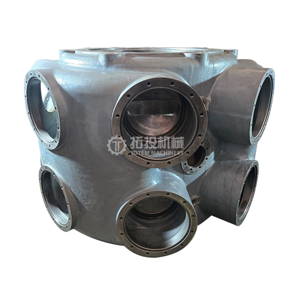
The cylinder provides the pressure-containing chamber in which suction, compression, and discharge occur. Its bore geometry, surface condition, cooling arrangement, valve location, and relationship with the piston affect sealing and gas flow. Wear or damage to the cylinder surface may contribute to leakage past the piston rings and reduced effective capacity.
A small space must remain between the piston and the cylinder head at the end of the stroke. This space is known as clearance volume, and it plays an important role in real compressor operation. Some high-pressure gas remains in that volume after discharge, so the next cycle does not begin with a completely empty cylinder.
Reciprocating compressor valves generally operate automatically in response to pressure differences. During suction, cylinder pressure drops below the suction-side pressure, allowing the suction valve to open. As compression begins, the pressure relationship reverses and the suction valve closes.
The discharge valve stays closed until cylinder pressure becomes greater than the pressure on the discharge side. It then opens and allows compressed gas to leave the cylinder. Valve condition directly affects how does a reciprocating compressor work in practice because leakage, delayed opening, restricted flow, or damaged valve elements can increase losses and reduce effective capacity.
The easiest way to understand the full operating cycle is to follow cylinder pressure and piston position through one revolution. In a simplified single-acting compressor, the main sequence consists of suction, compression, discharge, and re-expansion of gas trapped in the clearance space. This four-part view gives a more accurate explanation than reducing the process to only "intake and compression."
As the piston moves away from the cylinder head, cylinder volume increases and internal pressure falls. Once cylinder pressure becomes slightly lower than the suction-line pressure, the suction valve opens. Fresh gas then enters the cylinder while the discharge valve remains closed.
Gas continues entering until the piston approaches the end of the suction stroke. The amount actually admitted depends on factors such as suction pressure, gas temperature, valve behavior, operating speed, leakage, and clearance-related re-expansion. These influences help explain why real compressor capacity differs from an ideal geometric displacement calculation.
The crankshaft continues rotating and reverses piston direction. As the piston begins moving back toward the cylinder head, the suction valve closes and the gas becomes trapped inside the cylinder. Further piston movement reduces gas volume, so pressure and temperature increase progressively.
This stage is at the heart of how does a reciprocating compressor work. Both main valves remain closed during most of the compression period, allowing pressure to build rather than letting gas flow backward or escape prematurely. Effective sealing around the piston and piston rod is therefore essential to maintaining compression efficiency.
When cylinder pressure rises slightly above discharge-line pressure, the discharge valve opens. The piston continues toward the end of its stroke and forces high-pressure gas out of the cylinder. Discharge continues until the piston reaches the minimum-volume position.
Not all compressed gas leaves the chamber. A small amount remains in the clearance space between the piston and cylinder head. That residual high-pressure gas becomes important during the next suction stroke.
When the piston reverses direction, the residual gas in the clearance volume expands. The suction valve cannot open immediately because cylinder pressure is initially still above suction pressure. Fresh gas begins entering only after re-expansion reduces cylinder pressure sufficiently.
This effect is one reason clearance volume influences volumetric efficiency. A larger clearance volume leaves more residual gas available for re-expansion, which can reduce the portion of the piston stroke available for drawing in fresh gas. Clearance therefore has both mechanical and thermodynamic significance.
A single-acting compressor performs compression on one side of the piston. Gas is admitted and compressed in the same cylinder space while the opposite side does not function as an equivalent compression chamber. The arrangement is mechanically straightforward and is common in many smaller or less complex machines.
A double-acting compressor uses both sides of the piston for gas compression. As one side performs a compression or discharge function, the opposite side may be drawing in gas, depending on piston position. This arrangement can increase capacity for a given cylinder size, although it requires additional valves, sealing arrangements, and more complex gas passages.
The distinction helps answer how does a reciprocating compressor work across different industrial designs. The fundamental positive-displacement principle remains unchanged, but the number of active compression spaces per piston movement is different.
In a single-stage compressor, gas is compressed from suction pressure to final discharge pressure in one cylinder or compression stage. Multi-stage systems divide the total pressure increase across two or more stages. Gas discharged from one stage becomes the inlet gas for the next higher-pressure stage.
This staged approach is often used when a large overall pressure ratio is required. Dividing compression across stages can help control discharge temperature and allows intermediate cooling between compression steps. Cylinder sizes commonly become smaller at later stages because the gas occupies less volume after being compressed.
Compression raises gas temperature, and excessive temperature can increase thermal stress, affect lubrication, and reduce overall compression efficiency. An intercooler removes part of this heat before the gas enters the next stage. Cooler gas has a lower specific volume, which can reduce the work required for subsequent compression compared with allowing the gas to remain excessively hot.
Intercooling therefore adds another layer to how does a reciprocating compressor work in high-pressure service. The compressor is not merely moving pistons; it is managing pressure, temperature, gas density, sealing, and mechanical load across an integrated system.
Compressor efficiency is influenced by both mechanical losses and gas-path losses. A machine may have an accurately machined crankshaft yet still perform poorly if valves leak, piston rings allow excessive blow-by, clearance becomes unfavorable, or cooling is inadequate. Looking at the components together gives a more useful engineering picture.
| Component | Main Function | Potential Effect on Performance | Typical Concern |
|---|---|---|---|
| Crankshaft | Transfers rotational torque | Mechanical stability and friction | Wear, misalignment |
| Connecting rod | Transfers cyclic force | Motion accuracy and bearing losses | Bearing or pin wear |
| Crosshead | Guides linear movement | Alignment and side-load control | Guide wear |
| Piston rings | Seal piston-to-cylinder interface | Capacity and leakage control | Blow-by |
| Valves | Control inlet and discharge flow | Pressure losses and capacity | Leakage or restriction |
| Cylinder | Forms compression chamber | Sealing and volumetric performance | Surface wear |
| Packing | Seals around piston rod | Gas-loss control | Leakage |
| Cooling system | Removes compression heat | Temperature and efficiency control | Fouling or insufficient cooling |
This relationship is particularly relevant when evaluating how does a reciprocating compressor work under actual operating conditions rather than in an ideal diagram. Mechanical condition, gas sealing, valve response, and thermal management all influence how much input power becomes useful gas compression.
Wear does not only shorten component life; it can alter the thermodynamic and mechanical behavior of the compressor. A leaking suction valve, for example, can allow part of the compressed gas to flow back toward the suction side. Worn piston rings can permit blow-by, reducing the amount of gas effectively compressed and delivered.
Crosshead or guide wear may affect piston-rod alignment, while cylinder wear can compromise sealing at the piston interface. Crankshaft or bearing deterioration may increase vibration and mechanical losses. These relationships show why understanding how does a reciprocating compressor work is useful for maintenance diagnosis as well as basic equipment education.
Leaking suction valve: compressed gas can return toward the suction side.
Leaking discharge valve: high-pressure gas may flow back into the cylinder.
Worn piston rings: blow-by reduces effective compression and capacity.
Excessive clearance: more residual gas re-expands before fresh suction begins.
Poor alignment: packing, piston, crosshead, and guide wear may accelerate.
Reciprocating compressors are widely used where operators need controlled gas compression, relatively high pressure, or operation across a broad pressure range. Typical industrial services include natural gas compression, petrochemical processing, refinery operations, chemical production, refrigeration, process-gas handling, and other applications where gas must be compressed between defined suction and discharge conditions.
The exact machine design depends on gas composition, capacity, pressure ratio, temperature, operating duty, and plant requirements. A small single-stage compressor and a large multi-stage crosshead compressor may look very different, but the answer to how does a reciprocating compressor work is still based on the same positive-displacement cycle. Gas enters a cylinder, piston movement reduces its volume, valves control the direction of flow, and compressed gas is discharged into the downstream system.
Understanding how does a reciprocating compressor work requires more than identifying a piston moving inside a cylinder. The process begins with rotational power at the crankshaft, passes through the connecting rod and crosshead mechanism, drives the piston, and ultimately converts mechanical energy into increased gas pressure through positive displacement. Suction and discharge valves control gas direction, while clearance volume, sealing, cooling, lubrication, alignment, and component condition determine how efficiently the theoretical cycle is achieved in real operation.
For industrial reciprocating compressors, components such as the crankshaft, connecting rod, crosshead, piston rod, cylinder, and valve system should therefore be evaluated as parts of one coordinated mechanical system. Their geometry, condition, and interaction directly influence motion accuracy, leakage control, vibration, capacity, and long-term reliability. A technically complete understanding of the compression cycle provides a stronger basis for component selection, maintenance decisions, and troubleshooting than examining any single part in isolation.
A reciprocating compressor increases pressure by trapping gas inside a cylinder and reducing the available volume with a moving piston. As volume decreases, gas pressure rises until cylinder pressure exceeds discharge pressure. The discharge valve then opens and allows compressed gas to leave the chamber.
The crankshaft converts input rotational power into the motion required to drive the connecting rod. Together with the connecting mechanism, it produces the reciprocating movement transmitted to the piston. Its condition also affects vibration, bearing loading, and mechanical alignment.
A crosshead guides the reciprocating assembly along a controlled linear path. It separates the angular movement of the connecting rod from the piston rod and helps reduce lateral loading on the piston assembly. This arrangement is particularly useful in larger industrial compressors.
Single-acting compressors use one side of the piston for compression, while double-acting compressors use both sides. Double-acting designs can provide greater capacity for a given piston size but require additional valves and sealing arrangements. Both operate according to the same positive-displacement principle.
Intercooling removes heat after one compression stage before gas enters the next stage. Lowering gas temperature can reduce specific volume and help control the work and thermal load associated with subsequent compression. It also helps manage operating temperatures in high-pressure compressor systems.
Clearance volume contains residual high-pressure gas at the end of discharge. This gas expands during the beginning of the next suction stroke, delaying the point at which fresh gas can enter. Excessive clearance can therefore reduce volumetric efficiency and effective capacity.


