Views: 0 Author: Site Editor Publish Time: 2026-04-09 Origin: Site
Steam turbines convert thermal energy in steam into mechanical power for generators and industrial equipment. Their performance depends on the coordinated operation of stationary and rotating steam turbine components, including the casing, nozzles, diaphragms, rotor shaft, blades, bearings, seals, couplings, and auxiliary systems. Each part performs a specific function, but turbine reliability ultimately depends on how accurately these parts interact under changing pressure, temperature, speed, and load conditions.
For engineers, maintenance teams, and procurement professionals, understanding steam turbine parts is therefore more useful than simply identifying individual component names. Material compatibility, dimensional accuracy, rotor alignment, bearing condition, seal clearance, and manufacturing quality can all influence turbine performance. The following overview examines the turbine structure while also explaining how component design, inspection, application requirements, and replacement sourcing affect long-term operation.
| Component | Main Function | Engineering Importance |
|---|---|---|
| Casing / cylinder | Contains steam and supports stationary parts | Maintains the pressure boundary and structural alignment |
| Nozzle / diaphragm | Directs and accelerates steam | Controls steam flow and energy conversion |
| Rotor shaft | Supports rotating parts and transmits torque | Central to shaft-line stability and power transmission |
| Moving blades | Extract energy from steam | Convert steam energy into rotor torque |
| Bearings | Support and position the rotor | Control radial and axial rotor movement |
| Shaft seals | Restrict leakage and air ingress | Influence efficiency and vacuum integrity |
| Couplings | Connect shaft sections and driven equipment | Transfer torque through the shaft train |
| Turning gear | Slowly rotates the rotor during defined operating stages | Helps manage thermal distortion |
A turbine operates through the continuous interaction of stationary and rotating sections. Steam first passes through admission and control equipment before entering nozzles or stationary flow-path components, where part of its pressure energy is converted into velocity. The directed steam then acts on moving blades, creating force and torque on the rotor. Mechanical power is transmitted through the rotor and coupling to a generator, compressor, pump, or other driven equipment.
This operating sequence explains why steam turbine components cannot be evaluated independently. Bearings establish the rotor centerline, the casing supports stationary flow-path elements, seals control leakage around the shaft, and couplings maintain the mechanical connection between shaft sections. A change in alignment, clearance, or surface condition in one area can therefore affect several neighboring systems.
Stationary components form the structural and aerodynamic environment within which the rotor operates. They contain steam, guide the working fluid through successive stages, support bearings and internal hardware, and maintain the required relationship between fixed and rotating elements. Their design must account for pressure loading, thermal expansion, mechanical stress, sealing, and access for inspection or maintenance.
The turbine casing forms the primary pressure boundary around the steam path. Depending on turbine configuration, high-pressure (HP), intermediate-pressure (IP), and low-pressure (LP) cylinders may be arranged as separate sections, with each designed for the local steam conditions and mechanical requirements. Larger turbines may also use inner and outer casing arrangements to manage pressure loads and thermal gradients.
Thermal movement is a major consideration because turbine components expand as operating temperatures rise. Sliding keys, supports, locating features, and other structural references allow controlled expansion while helping maintain rotor-to-stator alignment. During maintenance or replacement work, casing joint surfaces, bores, locating features, and mating interfaces should therefore be assessed together rather than as unrelated dimensions.
Steam Turbine High Pressure Cylinder
Turbine Casing
Turbine Cylinder
Bearing Housings & Pedestals: Typically rigidly connected to the lower cylinder or foundation base, these structures utilize tilting-pad bearings. This design effectively eliminates oil film instability and suppresses self-excited vibrations.
Thrust Bearing System: High-performance thrust bearings are engineered to absorb immense axial thrust. They ensure zero axial displacement incidents, maintaining rotor stability even during millisecond-level transient conditions.
Tilting Pad Bearing
Din Bearing
Sliding Bearing
"A leak-free operation" remains the ultimate benchmark for modern turbines.
Advanced Seal Technology: Evolving beyond conventional labyrinth seals, we implement Brush Seals (Brydon type) and Honeycomb Seals. These innovations drastically minimize radial clearances, reducing inter-stage leakage losses by 15–20%.
Automated Gland Pressure Regulation: An intelligent system of steam admission and extraction automatically maintains optimal pressure. This guarantees zero steam leakage to the atmosphere across all load conditions, while simultaneously preventing air ingress into the vacuum system.
Rotating steam turbine components receive energy from the steam flow and transmit mechanical torque through the shaft train. Their design involves rotordynamics, material behavior, aerodynamics, fatigue resistance, manufacturing accuracy, and balance. Even small deviations in critical rotating parts can influence vibration and bearing loading at operating speed.
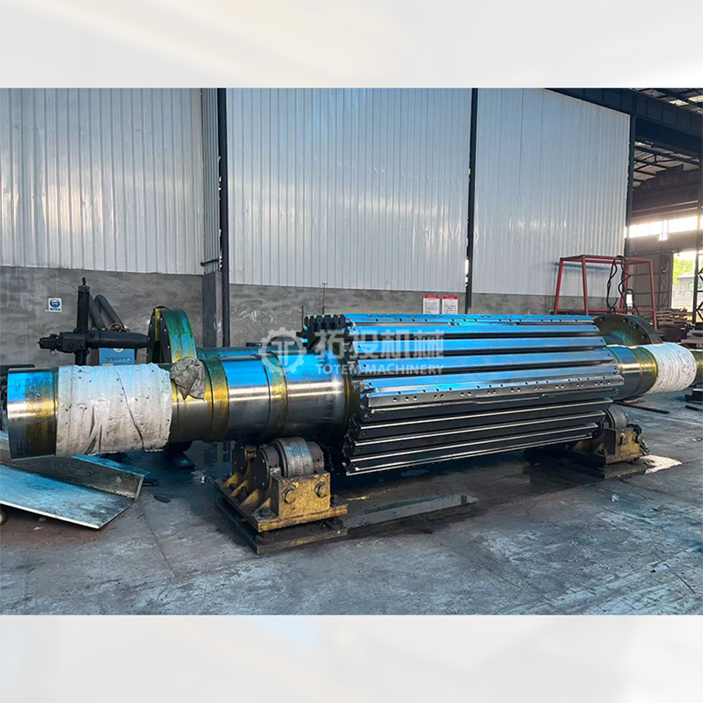
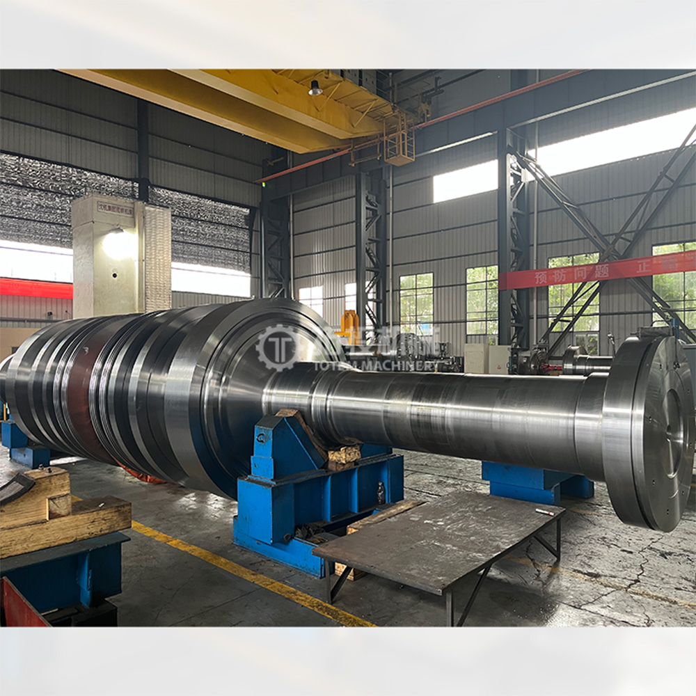
The rotor is the central rotating structure of the turbine. A steam turbine rotor shaft supports rotating elements, transmits torque, interfaces with bearings and seals, and connects with other shaft sections through couplings. Depending on turbine design, rotor construction may use an integral forged arrangement or a configuration in which selected components are assembled onto the shaft.
Material and manufacturing requirements vary with operating temperature, stress, rotational speed, and turbine section. During manufacturing or overhaul, critical inspection points can include journal surfaces, fillets, coupling interfaces, runout, concentricity, surface condition, and specified nondestructive testing. Replacement rotors should follow approved drawings and engineering requirements rather than being treated as dimensionally similar generic shafts.
Turbine Rotor Shaft
Steam Turbine Rotor Shaft
Steam Turbine Rotor Shaft Assembly
Deposition (PVD), and laser cladding: Structurally, blades are secured to the rotor disk via precision dovetail or fir-tree roots, often incorporating shroud bands or lacing wires to augment stiffness and dampen vibration.
Rigid Couplings: Ideal for systems requiring high alignment precision, offering a simple structure and high transmission efficiency.
The turning gear is a critical auxiliary system designed to safeguard the turbine rotor during startup and shutdown phases. Its primary function is to rotate the rotor slowly—typically at 3–10 rpm, either continuously or intermittently—after shutdown or before startup. This process prevents thermal bowing (also known as thermal eccentricity) caused by uneven temperature distribution across the rotor, thereby avoiding permanent deformation or excessive vibration upon startup.
The cornerstone of high-efficiency energy conversion lies in optimizing the turbine flow path. Critical components—such as blades and seals—are the primary determinants of flow efficiency. We specialize in the precision design and manufacturing of core flow-path parts, including blades, impellers, and diaphragms.
By employing full 3D optimization design, we engineer precision blades tailored to diverse steam parameters. Adhering to the thermodynamic principle of inverse pressure-volume relationships, we achieve progressive sizing optimization from the inlet to the exhaust. This includes using constant-section blades in the HP section for manufacturing efficiency and twisted blades in the LP section to accommodate varying flow parameters, thereby minimizing friction and vortex losses. Paired with multi-stage diaphragms and stationary cascades, we ensure precise matching of volumetric flow rates at every stage, guaranteeing smooth steam flow and full work extraction. This enables our turbines to consistently achieve a thermal efficiency exceeding 45%.
Steam Turbine
Turbine Rotor Shaft
Steam Turbine
Steam Turbine
We offer end-to-end customization services, aligning with client specifications from initial design and R&D through to production and delivery. This ensures perfect integration with the host machine, meeting diverse industry needs while enhancing equipment adaptability and operational ROI.
Digital Precision Casting: We operate digital production lines for precision blade casting, enabling end-to-end digital control from design to machining, significantly enhancing accuracy and efficiency.
Advanced Surface Treatment: Core components like blades and casings are treated with Thermal Barrier Coating (TBC) technology to boost heat and corrosion resistance, extending service life.
Modular Production: We employ a modular approach, breaking down complex turbines into standardized modules for batch production and rapid assembly, drastically shortening lead times.
b. Supply Chain & Logistics: We partner with top-tier global raw material suppliers, enforcing strict procurement and inspection standards to guarantee material quality. Our global logistics network is optimized for efficient warehousing and distribution, ensuring rapid and timely delivery tailored to client locations worldwide.
c.After-Sales Support: Our comprehensive service system offers installation guidance, troubleshooting, and maintenance support, eliminating operational concerns for our global clientele.
d. Conclusion: As a direct-to-source manufacturer, we anchor our value in core components. Through technological innovation, stringent quality control, customization, and global supply chain integration, we provide reliable support for turbine operations. We empower the energy sector to reduce costs, enhance efficiency, and achieve green development, continuously strengthening our core competitiveness to drive the high-quality, sustainable growth of the global energy industry.
Steam Turbine Rotor Shaft
Steam Turbine Rotor Shaft
Steam Turbine Rotor Shaft Assembly
Steam turbine components operate as an integrated system rather than as isolated parts. Casings and stationary flow-path elements guide and contain the steam, while rotors, blades, bearings, seals, couplings, and auxiliary systems convert and transmit mechanical power under demanding operating conditions. Reliable replacement decisions should consider function, interfaces, materials, manufacturing processes, inspection requirements, and application-specific duty. By combining accurate engineering information with controlled manufacturing and inspection, turbine owners can make more informed component sourcing and maintenance decisions.
The main steam turbine components include casings, nozzles or diaphragms, rotor shafts, moving blades, bearings, shaft seals, couplings, and turning gear systems. Their precise arrangement varies according to turbine type and operating duty. Together, these parts form the pressure boundary, steam path, and rotating shaft system required for energy conversion.
Stationary components contain or guide the steam and provide structural support, whereas rotating components receive steam energy and transmit mechanical torque. Casings, diaphragms, nozzles, and many sealing elements remain fixed, while rotors, shafts, and moving blades rotate. Bearings maintain the required position between the rotating and stationary systems.
Selection should begin with the turbine model, drawing revision, part position, operating duty, material requirements, and interfaces with neighboring parts. Manufacturing processes, inspection criteria, and documentation should also be confirmed before production. If reverse engineering is required, measured geometry should be separated from design information that still requires engineering verification.
Bearings maintain rotor position and support the oil film needed for stable rotation, while seals restrict steam leakage and unwanted air ingress. Problems in either area can influence vibration, temperature, efficiency, and neighboring clearances. Their condition should therefore be assessed together with alignment, lubrication, casing references, and rotor behavior.
A technically useful inquiry normally includes available drawings, turbine identification, component position, materials, critical dimensions, operating conditions, inspection requirements, quantity, and required documentation. Information about previous repairs or modifications can also be relevant. The more clearly the engineering interfaces are defined, the easier it is to evaluate replacement compatibility.


 Shaft sealing