
Views: 0 Author: Site Editor Publish Time: 2026-09-10 Origin: Site
Specifying the incorrect thrust bearing does more than cause localized component failure. It introduces catastrophic axial displacement. This aggressive movement can completely destroy expensive drivetrains. It often damages sensitive turbine assemblies beyond repair. Standard radial bearings handle perpendicular forces quite well. However, applications facing heavy axial loads require dedicated thrust solutions. These axial forces run entirely parallel to the shaft. They demand specialized geometries to absorb intense operating pressure.
This engineering guide bypasses basic introductory definitions. We offer procurement specialists a highly structured evaluation framework. You will learn to compare different bearing models. We teach you to assess strict operational limits. You will also uncover proven ways to mitigate installation risks. Choosing the proper component prevents dangerous unplanned downtime. We focus heavily on mechanical reliability and system longevity. By the end, you will confidently specify the exact bearing for your mechanical system.
Selecting the right thrust bearing requires balancing axial load capacity, maximum operating speed, and lubrication method.
Rolling element thrust bearings (ball and roller) are ideal for standard mechanical assemblies, while hydrodynamic fluid film bearings (like babbitt bearings) are necessary for extreme-mass, high-speed applications.
Over-specifying a thrust bearing can lead to skidding and premature failure due to insufficient minimum load requirements.
Accurate alignment and thermal management are the primary drivers of long-term bearing reliability.
Unmanaged axial forces cause immense friction inside mechanical assemblies. This friction generates excess heat rapidly. Unchecked heat inevitably leads to critical mechanical wear. Your primary goal involves transferring these loads seamlessly. The force must pass directly into the housing or foundation. Shaft rotation must remain entirely uncompromised during this transfer.
You evaluate success using strict operational metrics. An optimal selection minimizes systemic friction. It meets the required L10 fatigue life easily. The L10 metric dictates standard reliability expectations across the industry. The bearing must operate within defined thermal constraints. It also has to fit existing spatial limitations perfectly. When you balance these factors, mechanical longevity increases significantly.
Understanding the fundamental thrust bearing working principle is vital for proper specification. These components isolate and absorb axial loads exclusively. Axial loads run parallel to the axis of rotation. Manufacturers use distinct contact angles to manage this pressure. They also design specialized raceways to distribute stress evenly. Radial load management operates entirely differently. Standard radial bearings support forces perpendicular to the shaft. Interchanging these components causes immediate, disastrous mechanical failure.
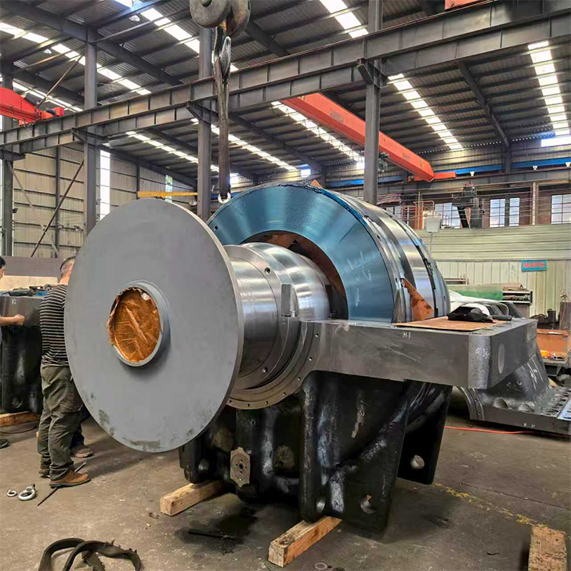
Engineers must evaluate various thrust bearing types carefully before finalizing designs. Each specific design handles unique operational limits. Choosing incorrectly compromises entire drivetrains immediately.
These components feature a precise point-contact design. The internal balls touch the raceway at a single point. This minimal contact area reduces friction significantly. They excel in high-speed, lower-load applications. You often see them inside aerospace components. Light automotive assemblies utilize them frequently.
However, ball designs carry distinct limitations. They remain highly susceptible to premature fatigue. Heavy shock loads easily dent the delicate raceways. Once dented, the bearing vibrates severely. You must avoid placing them in heavy industrial environments.
These variations utilize a robust line-contact design. The rollers distribute force across a wider surface area. This geometry handles extreme pressure effectively.
Cylindrical Rollers: They handle massive axial loads. However, they struggle under high speeds.
Tapered Rollers: These manage combination loads effectively. They require strict alignment during installation.
Spherical Rollers: This variant accommodates minor shaft misalignment safely. They forgive slight angular deviations.
You find roller designs in heavy-duty industrial applications. Giant plastic extruders and heavy crane hooks rely on them constantly. Their main limitation involves higher friction coefficients. Line contact generates more heat than point contact. You must provide rigorous, continuous lubrication to prevent melting.
These designs rely entirely on hydrodynamic wedge operation. They contain absolutely no rolling elements. Instead, they ride on a pressurized layer of oil. This oil film separates the metal surfaces completely during operation.
Engineers frequently specify a babbitt bearing for harsh, heavy-duty environments. The soft babbitt metal lining absorbs stray particulates safely. It embeds hard contaminants safely away from the rotating shaft. This material also provides crucial low friction during startup phases. Startup represents the most dangerous phase for bearing wear.
Shipbuilding relies heavily on specialized variations. A Marine Thrust Babbitt Bearing transfers massive propeller thrust directly to the hull. They utilize advanced tilt-pad designs. These pivoting pads adjust dynamically. They handle continuous, massive axial forces safely. Without them, large vessels would literally tear their own drivetrains apart.
Specification requires strict attention to operational metrics. You must evaluate four primary dimensions to ensure long-term reliability.
You must match the bearing capacity accurately against real-world forces. Continuous operational loads define your necessary dynamic rating. Dynamic ratings predict fatigue life under constant rotation. Conversely, shock loads determine your static rating requirements. Machines experience extreme impact forces during startup or sudden halts. Do not underestimate these peak impact forces. Exceeding the static load rating causes permanent raceway deformation.
High rotational speeds push internal rolling elements outward aggressively. Centrifugal force slams the rollers against the retaining cage. This friction generates extreme excess heat. It also alters critical internal contact angles. Over-speeding leads directly to rapid cage failure. Always verify the limiting speed rating in the manufacturer catalog.
You must compare lubrication methods carefully. The correct choice prevents overheating.
Grease Lubrication: Works perfectly for low-speed systems. It stays in place easily. It requires lower maintenance intervals.
Oil Bath Systems: Submerges part of the bearing in oil. Ideal for moderate speeds.
Circulating Oil: Required for high-speed systems. It actively dissipates heat. It flushes contaminants away from the contact zones.
Consider the physical footprint intimately. Seating arrangements matter immensely during installation. Flat seats require perfect perpendicular alignment. Any deviation causes immediate edge loading. Aligning seats offer more mechanical forgiveness. They utilize a spherical backing plate. This plate shifts slightly to accommodate minor shaft bending.
| Bearing Type | Contact Profile | Relative Speed Limit | Axial Load Capacity | Misalignment Tolerance |
|---|---|---|---|---|
| Ball Thrust | Point | High | Low to Moderate | Extremely Low |
| Cylindrical Roller | Line | Low | Very High | Low |
| Spherical Roller | Line | Moderate | High | High |
| Fluid Film (Babbitt) | Hydrodynamic Surface | Very High | Extreme | Moderate (Tilt-Pad) |
Even perfectly specified components fail under poor installation conditions. You must anticipate common implementation realities to protect your machinery.
Internal rolling elements must roll continuously. Insufficient axial load causes them to slide instead. Engineers call this destructive sliding "skidding" or "smearing." It destroys the highly polished bearing surface rapidly. It strips away the micro-layer of lubrication. Always maintain minimum load thresholds. If your system runs too light, consider adding pre-load springs.
Angular misalignment proves catastrophic for most designs. Standard cylindrical roller thrust bearings cannot handle it at all. The rollers pinch on one side. This pinch causes severe edge loading. The steel flakes away within hours. You should pivot to self-aligning spherical types immediately if alignment remains questionable. They forgive minor angular deviations naturally.
Harsh industrial environments carry severe particulate threats. Dust, water, and metal shavings ruin internal geometries. Contamination ingress acts like grinding paste. You must evaluate appropriate sealing configurations early. Labyrinth seals block debris effectively in high-speed applications. Contact seals work well for slower, highly contaminated environments. Clean lubrication represents your best defense.
Operating temperatures fluctuate wildly in heavy industry. Steel shafts elongate as they absorb heat. This thermal expansion causes unintended axial preload. If the housing traps the bearing, the system binds entirely. The resulting friction melts the cage. You must account for linear growth during the initial design phase. Leave adequate clearance for thermal expansion.
Follow a systematic shortlisting process. This framework eliminates guesswork and ensures mechanical compatibility.
Define your exact operating parameters first. Measure the expected axial load in kilonewtons (kN). Calculate your maximum continuous RPM. Identify your maximum and minimum operating temperature ranges accurately. You cannot select a component without these foundational numbers.
Eliminate incompatible designs immediately. Some components exceed the available housing envelope. Others cannot integrate successfully into existing shaft dimensions. Match the internal bore directly to your existing shaft designs. Ensure the outer diameter fits the housing smoothly.
Weigh the upfront integration requirements heavily. Advanced tilt-pad babbitt designs require highly specific oil delivery housings. However, they offer incredibly long maintenance intervals. They rarely fail if kept supplied with clean oil. Cheaper rolling element alternatives install easily. Yet, they might increase future operational downtime. They require frequent grease repacking. They also suffer from finite metal fatigue limits. Evaluate the long-term maintenance impact on your production schedule.
Compile all system specifications into a single document. Consult application engineers immediately. You can also utilize manufacturer sizing calculators online. Enter your baseline physics data. Always verify dynamic load capabilities against manufacturer charts before procurement. Do not guess.
Selecting a thrust bearing remains an exercise in operational compromise. You must carefully balance load capacity, rotational speed, and lubrication capabilities. This delicate balance ensures systemic mechanical reliability. Ignoring minor misalignments leads directly to major failures. Every engineering choice impacts drivetrain longevity permanently.
Proper specification prevents costly, dangerous machine shutdowns. Review your static and dynamic loads thoroughly. Evaluate your environmental contamination risks. Download our specific technical catalog today for detailed sizing charts. You can access our online CAD model configurator for exact dimensional planning. Alternatively, contact the engineering support team immediately. They provide comprehensive application reviews to guarantee your success.
A: Generally no, unless specifically designed as an angular contact thrust bearing. Standard designs solely isolate forces parallel to the shaft. You usually need separate radial bearings to manage perpendicular forces safely.
A: They fail primarily due to poor lubrication, severe angular misalignment, and operating below minimum load thresholds. Insufficient load causes skidding. Contamination ingress also accelerates raceway degradation rapidly.
A: A babbitt bearing utilizes hydrodynamic fluid film operation. It contains no rolling elements. Roller thrust bearings rely on physical steel rollers. Babbitt designs excel in massive-load, high-speed applications where rollers would fatigue.
A: You define the equivalent dynamic bearing load first. Then, you establish the desired rating life (L10). You match these load calculations against manufacturer catalog ratings to find the proper physical dimensions.


