
Views: 0 Author: Site Editor Publish Time: 2026-09-13 Origin: Site
Heavy machinery faces immense operational forces daily. Turbines, compressors, and marine drives rely on precise load management. Proper load management prevents catastrophic rotor crashes. It also reduces unplanned downtime. Engineers often misunderstand the core bearing selection process. We do not simply choose between bearing types for the same task. Instead, the real decision requires correctly identifying load vectors. You must analyze axial and radial forces accurately. Then, you can specify the exact bearing assembly to handle those forces. We will explore the technical evaluation of both bearing types. You will discover their functional overlap in high-speed applications. We also provide a complete specification framework. This guide guarantees a reliable equipment lifecycle. Mastering these principles protects your critical rotating assets.
Load Direction dictates selection: Journal bearings support radial loads (perpendicular to the shaft); thrust bearings support axial loads (parallel to the shaft).
Hydrodynamic principles apply to both: Both bearing types often rely on a pressurized fluid film to eliminate metal-to-metal contact during operation.
Material continuity: A babbitt bearing is not a separate category; Babbitt metal is the standard lining applied to both journal and thrust configurations for optimal friction reduction.
System integration: High-capacity rotating equipment typically requires a combined assembly (one thrust bearing and multiple journal bearings) to restrict movement in all dimensions.
Rotating shafts generate complex forces during operation. These multi-directional forces depend on rotational speed, rotor weight, and driven loads. Properly supporting a heavy rotor requires isolating these forces. We categorize these operating forces into two distinct vectors. Understanding these vectors prevents premature equipment failure.
Radial loads push perpendicular to the center of the shaft. Gravity creates the most common radial load. Horizontal shafts push down heavily on their supports. Imbalanced rotors also generate severe radial forces. These forces radiate outward as the shaft spins. Engineers deploy journal bearings to manage these perpendicular stresses. The bearing surrounds the shaft and holds it exactly in place. They prevent the shaft from shifting up, down, or sideways.
Axial loads act parallel to the shaft line. They push forward or backward along the axis of rotation. Certain machinery naturally generates massive axial forces. Helical gears push horizontally when they interlock. Industrial pumps generate forward suction forces. Ship propellers push massive amounts of water backward. This action forces the entire shaft forward. Thrust bearings capture these linear forces. They anchor the shaft and prevent horizontal drift.
Miscalculating the load direction causes immediate mechanical disaster. You cannot force a component to perform outside its design geometry. Applying axial thrust to a standard journal design causes rapid edge-loading. The shaft digs into the edge of the bearing lining. Catastrophic material failure follows instantly. You must properly identify the primary load vector before analyzing the thrust bearing vs journal bearing dynamic.
Heavy industries rely heavily on fluid film technology. A hydrodynamic journal bearing generates a self-sustaining oil wedge. The spinning shaft acts like a pump. It drags lubricating oil into a narrowing clearance space. This creates an area of extreme pressure. The fluid pressure lifts the shaft completely off the metal surface.
These components offer exceptional dampening capacity. The oil film absorbs heavy rotor vibrations smoothly. It acts like a hydraulic shock absorber. This bearing type has an infinite theoretical lifespan. The shaft and bearing never physically touch during normal operation. They easily handle extreme rotational speeds. Many high-speed compressors rely exclusively on this hydrodynamic phenomenon.
Despite their capabilities, fluid film systems carry specific operational risks. Engineers must carefully monitor operational variables to prevent damage.
Startup and Shutdown Wear: Machinery faces the highest risk of boundary lubrication here. Metal-to-metal contact occurs before the shaft spins fast enough. The hydrodynamic wedge cannot form at low speeds. Operators often use hydrostatic lift pumps to protect the surfaces during startup.
Oil Whirl and Whip: Lightly loaded shafts operating at high speeds face instability. The fluid film can drive the shaft into an orbital vibration. This is known as oil whirl. Left unchecked, it progresses into destructive oil whip.
Clearance Tolerances: The oil wedge requires strict geometric clearances. You must maintain precise oil viscosity and operating temperatures. Too much heat thins the oil. This collapse destroys the fluid wedge instantly.
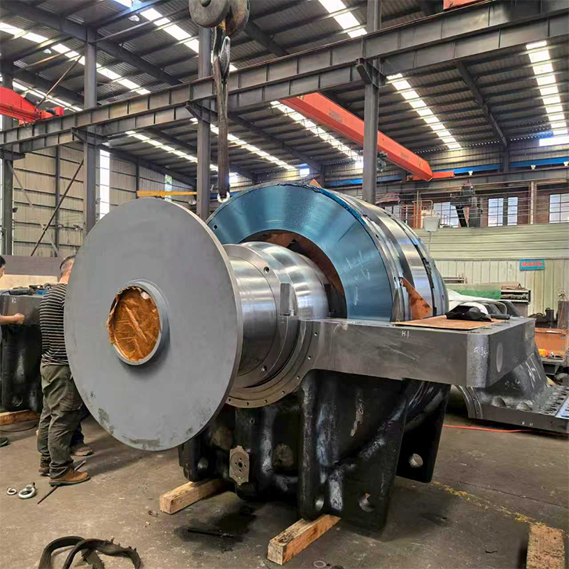
Horizontal shaft drift destroys internal machine components. You must lock the rotor axially to protect impellers and seals. Thrust assemblies use specialized profiles to manage these parallel forces. They utilize the same hydrodynamic principles to separate moving parts.
Fixed geometry designs feature flat or tapered lands. They are simple, durable, and cost-effective. However, they struggle with severe shaft misalignment. Tilting pad thrust bearings solve this specific problem. Each pad pivots independently on a spherical pivot point. They automatically adjust their angle based on fluid film pressure. This dynamic adjustment handles massive loads perfectly. It easily compensates for minor structural deflections.
Marine applications present unique axial challenges. A ship’s propeller generates continuous, massive forward thrust. This force must transfer safely to the ship's hull. A specialized Marine Thrust Babbitt Bearing handles this exact requirement. It absorbs extreme forward propulsion forces directly from the propeller shaft. It maintains strict running tolerances while operating in a low-friction hydrodynamic state. This assembly ensures the vessel moves efficiently without destroying the engine block.
Thrust configurations face unique lubrication challenges. Centrifugal forces actively fight the oil film. High rotational speeds throw lubricating oil outward. The oil moves away from the critical bearing faces. This causes severe lubrication starvation at the inner diameter. You must design specialized oil delivery systems. Directed lubrication sprays oil directly onto the leading edge of each pad. This ensures consistent cooling and load support.
Many engineers treat Babbitt as a separate bearing category. This is an incorrect assumption. A babbitt bearing simply refers to the surface material. Babbitt metal is the critical sacrificial lining. Manufacturers apply it to both journal and thrust configurations. Isaac Babbitt invented this tin and lead-based alloy in 1839. It remains the industry standard for optimal friction reduction today.
Babbitt alloys offer two critical mechanical advantages. They protect expensive rotor shafts from catastrophic damage.
Conformability: Heavy rotors often experience microscopic shaft misalignments. Babbitt metal yields slightly under localized pressure. It physically adapts to the shaft profile over time. This minimizes highly localized stress concentrations.
Embeddability: Oil systems inevitably carry foreign particulates. Dirt, rust, and wear debris flow through the lubrication channels. Hard bearings would grind these particles against the shaft. Babbitt safely traps and embeds these particles below the surface. This prevents severe shaft scoring.
You must respect the operational limits of Babbitt alloys. They yield quickly at high temperatures. Most standard alloys lose structural integrity above 150°C (300°F). They will melt or wipe under extreme heat. System cooling is a mandatory specification criterion. You must guarantee adequate oil flow at all times. The oil does not just lubricate the system. It acts as the primary cooling medium. It carries heat away from the friction zone.
Procuring reliable bearing solutions requires a disciplined engineering approach. Purchasing teams cannot buy these components based purely on price. They must evaluate technical success criteria thoroughly. We provide a proven framework to guide your selection process.
Technical Comparison of Load Profiles
| Characteristic | Journal Configurations | Thrust Configurations |
|---|---|---|
| Primary Load Vector | Radial (Perpendicular) | Axial (Parallel) |
| Typical Applications | Horizontal Shafts, Motors | Pumps, Marine Propellers |
| Common Pad Designs | Cylindrical, Lemon Bore | Tapered Land, Tilting Pad |
| Primary Failure Mode | Oil Whirl, Startup Wear | Lubrication Starvation |
Follow these specific steps to match bearing designs to operational demands. Accurate data collection prevents premature mechanical failures.
Maximum Load Capacity: Calculate the exact unit load during operation. Measure this in PSI or MPa. You must evaluate both steady-state loads and transient shock loads. Ensure the specific bearing geometry can handle peak pressures.
Surface Speed: Determine the exact shaft RPM. Surface speed dictates the lubrication mechanism. High speeds easily generate a hydrodynamic film. Very low speeds require forced hydrostatic lubrication systems to prevent friction.
Lubricant Specifications: Match your bearing design to your plant's oil standards. Verify oil viscosity grades. Calculate required flow rates and system cooling capacities. Ensure the heat exchanger can handle the thermal load.
Clearance & Misalignment Tolerances: Anticipate structural deflection under heavy loads. Select tilting-pad designs over fixed designs when misalignment is likely. Ensure the final housing footprint accommodates these complex dynamic assemblies.
Theoretical load calculations only represent the first phase. You must transition from paper math to physical reality. Partner closely with a custom bearing manufacturer or original equipment manufacturer (OEM). Share your exact housing footprints and API standard requirements. Collaborative engineering ensures the final assembly fits perfectly into your existing machinery.
Reliable rotating machinery requires accurate load vector management. You must correctly match journal assemblies to radial loads. You must also assign thrust assemblies to axial loads. High-capacity equipment often combines them into a single integrated housing. This restricts movement in all three dimensions perfectly.
Bearing failure is rarely a manufacturing defect of the bearing itself. It is usually a symptom of a larger system flaw. Improper load calculations cause rapid physical destruction. Lubrication failures and incorrect material specifications destroy the critical fluid film. You must monitor system health constantly.
Engage your engineering support team today. Audit your current machinery failure modes thoroughly. Review your site's lubrication parameters and cooling capacities. If you notice unusual vibration or heat, take immediate action. Quote custom or replacement assemblies before a catastrophic rotor crash occurs.
A: The main difference is the specific load direction they support. Journal designs support radial loads pushing perpendicular to the shaft. Thrust designs support axial loads pushing parallel to the shaft line.
A: Yes, flanged journal bearings can handle both. They feature a cylindrical bore for radial loads and flanged faces for axial forces. However, they only handle light to moderate axial loads effectively in high-speed scenarios.
A: Failure usually results from the collapse of the oil film. Common causes include oil contamination, improper fluid viscosity, excessive operating temperatures, and severe boundary friction during slow machine startups.
A: Ships generate massive, continuous forward force from the propeller. These specialized components absorb this extreme axial load safely. They transfer the propulsion force to the hull while maintaining a low-friction hydrodynamic state.


