
Views: 0 Author: Site Editor Publish Time: 2026-08-01 Origin: Site
Marine propulsion shaft misalignment rarely announces itself with one unmistakable alarm. A rising bearing temperature, load-dependent vibration, abnormal wear, or a change after ballasting can each point toward alignment trouble, but each can also have other causes. The practical task is to connect symptoms with operating condition, bearing reaction, shaft geometry, and recent vessel changes before local contact develops into bearing damage.
Diagnosis therefore has to compare the shaftline at rest with the shaftline in service, using measurements in a logical sequence that separates static alignment errors from thermal movement, hull deflection, lubrication problems, and component condition.
The most useful shaft misalignment symptoms are patterns rather than isolated readings. Bearing temperature is a common example. A bearing that becomes consistently hotter after loading changes, machinery work, or operation at certain propulsion conditions deserves investigation. However, temperature alone cannot distinguish misalignment from inadequate oil supply, contamination, unsuitable clearance, cooling problems, or another lubrication-related fault.
Temperature may also rise only after unfavorable shaft-to-bearing contact has already developed. Waiting for a high-temperature alarm before investigating marine shaft alignment can therefore allow wear to progress further than necessary.
The same caution applies to vibration. Alignment-related vibration may change with shaft speed, torque, vessel draft, maneuvering condition, or machinery temperature. A vibration increase that appears only after the engine room reaches operating temperature can be more diagnostically useful than one high reading at a single speed. Changes in phase, bearing housing response, operating load, and comparison with historical baseline data should be considered together.
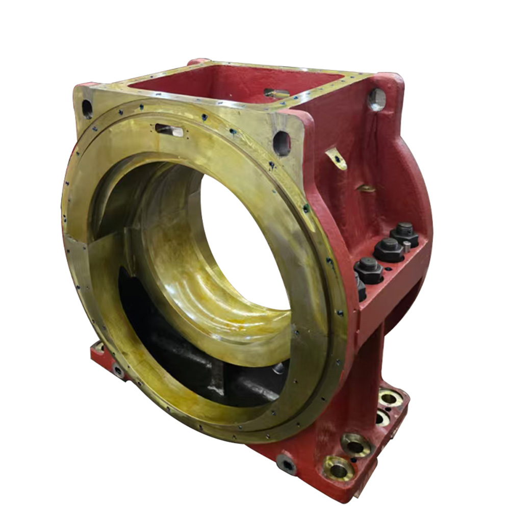
An Intermediate Shaft Bearing supports radial shaft load and works with the shaft, bearing structure, and lubrication system to maintain the shaftline's operating position. Uneven bearing reaction or unfavorable shaft-to-bearing contact can therefore become an important clue that the problem involves alignment rather than simple rotating imbalance.
| Observation | What It May Indicate | Why It Is Not Enough Alone |
|---|---|---|
| Local bearing temperature rise | Edge loading or excessive bearing reaction | Lubrication or cooling problems can create similar heating |
| Vibration changing with load or draft | Shaftline geometry affected by operating condition | Propeller excitation and imbalance may also vary |
| Abnormally high or low bearing reaction | Load redistribution between supports | The result must be compared with the expected condition |
| Uneven bearing wear or contact | Persistent unfavorable shaft slope or loading | Wear may remain from an earlier alignment condition |
| Symptoms after repair, grounding, or machinery movement | Changed shaft, foundation, or bearing position | The actual geometric change still requires measurement |
A stronger diagnosis appears when two or more independent observations point in the same direction. For example, a temperature increase at one bearing combined with an abnormal measured reaction and a change after ballasting is far more persuasive than temperature alone.
A shaftline can satisfy a cold marine shaft alignment check and still develop unfavorable bearing loads during operation. Hull flexibility, vessel loading, draft, machinery thermal growth, bearing pedestal movement, and hydrodynamic propeller forces can all change the shaft-to-bearing relationship after the initial static condition.
This distinction changes the diagnostic question. Do not ask only whether the shaft appears aligned while the vessel is stationary. Ask under which vessel condition the alignment was measured and whether the shaftline continues to maintain acceptable bearing-load distribution as temperature, loading, and operating condition change.
The Marine Intermediate Shaft forms part of the torque-transmitting shaftline and operates together with adjacent shaft sections and supporting bearings. Journal geometry, flange interfaces, runout, and the relationship between the shaft and support positions should therefore be considered when determining whether an apparent alignment problem originates in shaft geometry or in the installation around it.
Cold measurements establish a reference when machinery is stopped and temperatures have stabilized. They are useful for checking shaft geometry, bearing offsets, flange relationships, foundation positions, and comparison with installation calculations.
A common mistake is expecting every bearing, coupling, and shaft section to lie on one perfectly straight geometric centerline. Propulsion shaft alignment is normally evaluated with shaft deflection and required bearing reactions in mind. An intentional bearing offset may therefore be part of the correct arrangement rather than evidence of poor installation.
Once machinery warms up and the vessel changes draft or loading condition, the relative elevations of the engine, gearbox, bearings, and stern structure can shift. Propeller loading and maneuvering can further alter shaft curvature and bearing contact during service.
A useful diagnostic comparison should record the operating condition alongside each measurement. Relevant information may include vessel draft, ballast or cargo state, machinery temperatures, shaft speed, propulsion power, and maneuvering condition. Without this context, cold and operating measurements cannot be compared reliably.
No single propulsion shaft alignment method answers every diagnostic question. Geometry measurements show where components are positioned. Bearing reaction measurements show how shaft weight and bending load are distributed. Operating monitoring reveals what changes after the static alignment procedure is complete.
| Method | Best Diagnostic Use | Main Limitation |
|---|---|---|
| Bearing load measurement | Identifying overloaded, lightly loaded, or unexpectedly unloaded supports | Requires comparison with expected reactions for the same condition |
| Sag and gap method | Checking relative flange position before coupling | Strongly influenced by measurement condition and hull deformation |
| Laser or optical alignment checks | Establishing geometric position and centerline relationships | Geometry alone does not prove acceptable bearing loading |
| Runout and journal checks | Separating shaft geometry problems from installation offsets | Does not directly measure bearing reaction |
| Temperature and vibration trending | Detecting changes during operation | Signals are not unique to misalignment |
Bearing load measurement is valuable because marine propulsion shaft misalignment is fundamentally a load-distribution problem as well as a geometric problem. A bearing can appear correctly positioned but still carry an unexpectedly high or low reaction because the shaftline bends across several supports.
The important comparison is measured bearing reaction versus the expected reaction for the same vessel loading, temperature, and machinery condition. Comparing an afloat hot measurement directly with a drydock cold target can produce the wrong conclusion if the difference in operating condition is ignored.
Bearing load measurement becomes particularly valuable when geometry appears acceptable but temperature or vibration trends remain abnormal. An overloaded, lightly loaded, or nearly unloaded bearing may indicate that shaft curvature or support position is distributing load differently from the intended condition.
The sag and gap method examines the relative vertical displacement and angular relationship between uncoupled mating flanges. It is particularly useful during shaftline installation or reassembly because flange readings can be compared with calculated target values.
A common mistake is assuming that zero sag and zero gap are always the correct objectives. The proper values depend on shaft deflection, bearing offsets, flange location, and the vessel condition used for the alignment calculation.
Measurements taken afloat also require caution because hull deformation may differ from the condition in which the original targets were established. If flange geometry appears acceptable but bearing reactions remain abnormal, further investigation should focus on bearing elevation, foundation behavior, shaft stiffness, wear, thermal growth, and operating-condition effects instead of repeatedly adjusting coupling positions.
A disciplined diagnostic sequence helps prevent technicians from moving a bearing before knowing whether that bearing is actually the cause. It also reduces the risk of correcting a cold static reading while making the hot operating condition worse.
Establish whether the problem occurs immediately after startup, after thermal stabilization, at a particular shaft speed, above a specific propulsion load, during maneuvering, or after a loading-condition change. Compare current behavior with previous trends and, where appropriate, compare similar port and starboard systems.
A problem present immediately under nearly every condition points toward a different group of causes from one that appears only after several hours of thermal growth. Defining the operating window first makes later measurements much easier to interpret.
Before changing shaft alignment, confirm lubricant supply, oil condition, bearing clearance, cooling, visible wear, bearing-shell seating, pedestal condition, and fastening integrity.
Misalignment can damage a bearing, but a damaged, worn, poorly lubricated, or poorly supported bearing can also alter the shaft's working position. This distinction prevents a costly diagnostic mistake: moving an otherwise correctly positioned bearing to compensate for a local bearing or lubrication fault.
Review recent drydocking, bearing replacement, coupling work, engine or gearbox chocking, stern repairs, foundation work, grounding, propeller work, or major structural repair. Also compare the vessel's present draft and loading condition with the condition in which the previous shaft alignment was verified.
Hull deflection and changing vessel conditions can alter propulsion shaft behavior even when no shaft component has obviously shifted. A timeline of recent mechanical and structural work can therefore narrow the investigation considerably.
Measure relevant shaft journals, coupling faces, runout, bearing locations, and flange relationships, then compare those results with bearing reaction measurements.
This is the decision point that separates “the shaftline geometry has changed” from “the geometry appears similar, but the load distribution has changed.” If both geometry and bearing reactions have shifted, inspect foundations, chocks, bearing seating, and structural changes. If geometry remains similar while reactions change, operating condition, bearing stiffness, wear, lubrication, or thermal effects deserve closer attention.
A repair decision should not be based only on a convenient dockside measurement if the symptom occurs exclusively underway. After static checks, the shaftline should be verified under the relevant thermal and vessel-loading conditions whenever the applicable procedure allows.
The objective is not simply to obtain acceptable workshop measurements. It is to establish propulsion shaft alignment that maintains suitable shaft-to-bearing interaction throughout the operating conditions for which the system is intended.
Corrective action should depend on what the diagnostic sequence proves. If a bearing has moved because of foundation or chock deterioration, the support condition should be restored before arbitrary bearing-offset adjustment. If bearing wear has changed the journal position, the bearing condition and clearance should be corrected.
If thermal growth or hull deflection causes the operating problem, simply returning the cold shaftline to a visually straight condition may reproduce the same failure once the vessel is operating again.
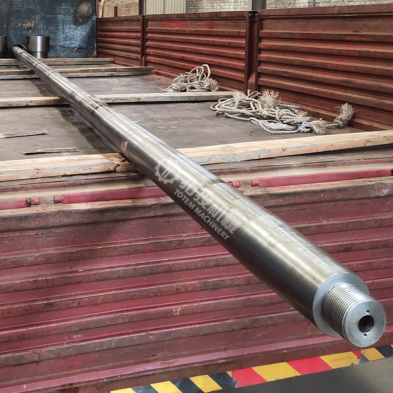
The dimensional condition of the Marine Propeller Shaft should also be considered when the investigation points toward the aft shaftline. Journal accuracy, coupling interfaces, coaxiality, runout, and overall shaft geometry influence component fit and the interpretation of alignment measurements.
Adjustment should be driven by calculation and measurement together. Raising or lowering one intermediate bearing redistributes reaction among several supports. Improving the reading at one bearing can therefore increase loading somewhere else.
This is why propulsion shaft alignment should be treated as a complete system problem rather than a series of independent bearing adjustments.
After correction, repeat the measurements that originally identified the problem. Verify bearing reactions, relevant flange or geometric readings, temperature behavior, and vibration under comparable conditions. If the original symptom was load-dependent or temperature-dependent, confirmation should include the same operating window.
A repair is not fully demonstrated by an acceptable cold reading when the damaging condition existed only after thermal stabilization or during actual vessel operation.
Marine propulsion shaft misalignment is most reliably diagnosed by connecting symptoms, vessel condition, bearing loads, shaft geometry, and cold-to-operating changes instead of reacting to one temperature or vibration reading. Measurement sequence matters because premature bearing adjustment can hide the real cause or transfer excessive load elsewhere.
Shanghai TOTEM Machinery Co., Ltd. is a manufacturer of marine shafting and bearing components. Accurate shaft and bearing geometry provides an essential foundation for propulsion shaft alignment, while reliable operation still depends on correct installation, system-level measurement, and verification under relevant vessel conditions.
A: Useful early indicators include changing bearing reaction, load-dependent vibration, localized temperature trends, or altered behavior after ballasting or machinery work. None should be treated as proof alone.
A: Yes. Thermal growth, hull deflection, vessel loading, and propeller forces can change shaft curvature and bearing loads after machinery reaches operating conditions.
A: No. Insufficient lubrication, contamination, clearance problems, cooling faults, or bearing damage can also raise temperature, so other measurements should confirm the cause.
A: It shows how shaft reaction is distributed among supporting bearings, helping identify overloaded or underloaded supports that may not be obvious from geometric alignment checks alone.
A: It is mainly useful for checking uncoupled flange relationships during installation or reassembly, provided measured values are compared with calculated targets for the relevant vessel condition.
A: Not usually. First establish whether the cause is bearing position, wear, foundation movement, shaft geometry, hull deflection, thermal growth, or lubrication before changing an offset.


