| Availability: | |
|---|---|
| Quantity: | |
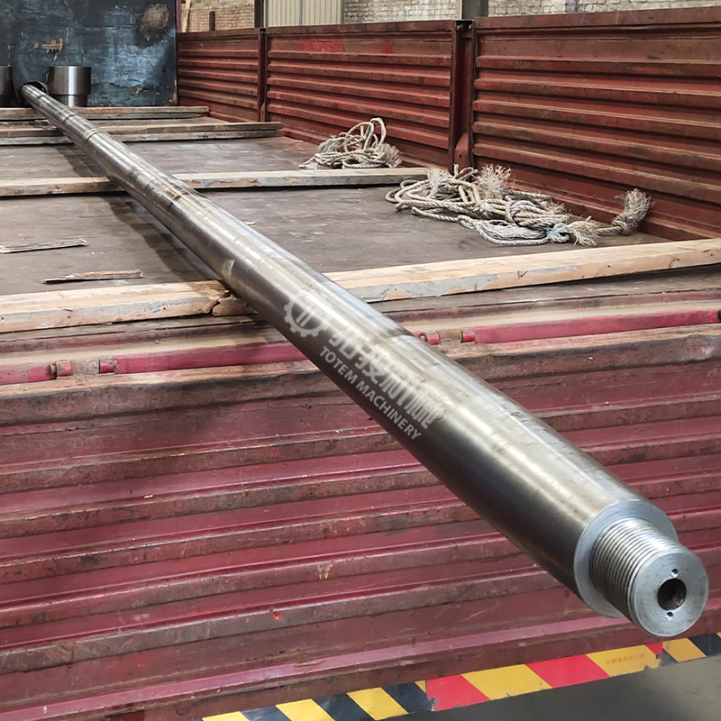
The propeller shaft is a core component of the marine propulsion system. It is installed between the main engine and the propeller, and is primarily responsible for power transmission — transmitting the torque output by the motor stably to the propeller to achieve continuous propulsion of the vessel. As one of the core components, its operating condition directly affects the transmission efficiency, operational stability, and service life of the entire marine propulsion system.
Due to the propeller shaft operating under prolonged low-speed, high-torque, and continuously alternating load conditions, combined with marine environmental factors such as humidity, salt spray, and vibration, stringent requirements are imposed on its material properties, structural strength, and machining precision. The propeller shaft is usually made of superior forging steel or high-strength alloy steel. These materials offer good comprehensive mechanical performance and fatigue resistance. While ensuring load-bearing capacity, they also demonstrate superior stability and long-term operational reliability.
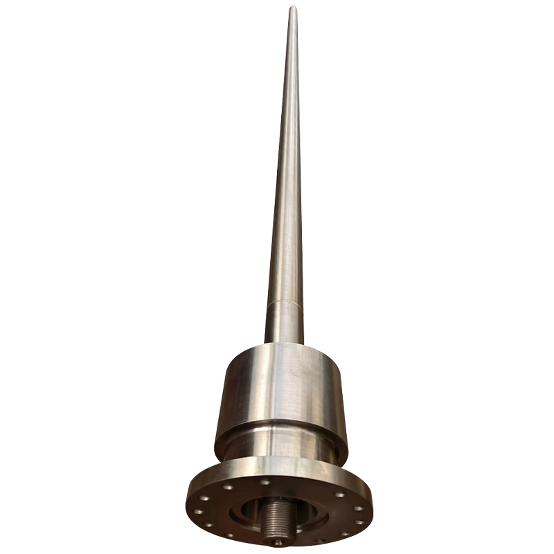
Structurally, the propeller shaft typically consists of the shaft body, the coupling connection section, and the propeller mounting end. Each section must maintain proper fit with the coupling, bearing, seal gland, and other related parts. Strict control is required over axial diameter dimensions, end face accuracy, coaxiality, and transition section dimensions during machining to ensure assembly accuracy and operational stability.
The screw shaft is widely used in cargo ships, engineering vessels, offshore platforms, and various marine propulsion systems. Our company provides custom machining according to different vessel types, transmission power, and installation requirements.
Propeller Shaft
Propeller Shaft
Propeller Shaft
The propeller shaft is a type of large-scale shaft component. It requires a long machining cycle and demands high levels of equipment rigidity, process control, and machining experience. The entire manufacturing process typically progresses through rough machining, semi-finishing, and finishing stages to ensure dimensional stability and axis alignment consistency.
The tailshaft is first turned on a large lathe, cutting the outer diameter, shoulders, and different functional sections step by step. During machining, the center holes or reference surfaces serve as the locating points. As material is gradually removed, each shaft section is brought to the required dimensions per the process specifications, with smooth transitions maintained between sections.
During turning operations, emphasis should be placed on controlling dimensional accuracy, roundness, and surface finish of the outer diameters. At the same time, real-time adjustments are made to compensate for deformation during machining of the long-shaft component, ensuring axial stability.
Propeller Shaft
Propeller Shaft
Propeller Shaft
The coupling is a critical assembly component of the propeller shaft. During rough machining, the primary tasks include processing the outer diameter of the connecting end, the end face, and the base connection dimensions, with machining allowance reserved for subsequent precision operations. Special attention must be paid to end face perpendicularity and dimensional consistency at the connection points to provide a reliable foundation for final coupling assembly.
Coupling
Coupling
Coupling
After finish machining, the propeller shaft must undergo a complete inspection process to ensure the product meets the usage requirements of the marine propulsion system.
Shaft diameter dimensions, length dimensions, end face dimensions, and critical fit areas are inspected. At the same time, run-out, coaxiality, and straightness of the shaft are checked to ensure all technical parameters comply with drawing specifications.
Through trial assembly with the coupling, the fit condition of the connection joints is inspected to confirm that assembly dimensions, contact conditions, and connection accuracy meet the requirements.
Propeller Shaft
Propeller Shaft
A weight inspection is performed on the finished product after machining to verify product data and provide a reference for subsequent hoisting, transportation, and on-site installation.
Propeller Shaft
Coupling
Before the propeller shaft is exported, the entire machined surface is cleaned and anti-rust oil is applied. Protective materials are used to cover the journal, coupling mating surfaces, and threaded areas to prevent impacts, scratches, or surface corrosion during transportation.
Depending on the dimensions and shipping method of the propeller shaft, wooden pallets are typically used for support, along with localized fixation and external steel structure reinforcement.
Propeller Shaft
Propeller Shaft
Coupling
Diagnose reciprocating compressor crosshead wear to prevent costly downtime. Master clearance inspections and repair vs. replacement strategies.
Selecting reciprocating compressor cylinder material is vital for safety and life-cycle cost. This article compares three cast families: iron (grey/ductile), steel (carbon/low-alloy), and stainless (austenitic CF8M/CF3M, martensitic 17-4PH). It examines strength, hardness, thermal conductivity, expansion, self-lubrication, corrosion resistance, weldability, and failure modes (wear, corrosion, cracking, creep).
This article analyzes small crankshaft manufacturing for reciprocating compressors. These core components endure alternating loads over 200 MPa, speeds to 3000 r/min, thin oil film, and -20 to 80°C temperatures. Material choice prioritizes 40CrNi2MoA for fatigue strength, with 42CrMo as economic alternative. Process includes die forging (ratio >=3), quenching/tempering to 28-34 HRC core, surface hardening to 54-58 HRC, and precision machining to IT7, Ra <=0.4 μm. Quality control covers dimensions, hardness, MPI, UT, with three-level inspection. Failure prevention targets fatigue, wear, cracking, and imbalance. A case study achieved 99.5% yield. Cost breakdown shows machining as largest share; batch optimization and near-net-shape forging reduce costs. Trends include laser hardening, 3D repair, in-process sensing, composites, and green quenchants. Zero-defect production integrates materials, heat treatment, precision machining, and quality management for reliable compressor operation.
Professional guide to the casting and assembly of reciprocating compressor cylinder blocks. Covers key casting difficulties, systematic process solutions, core assembly challenges, and rigorous testing procedures to ensure stable and reliable cylinder performance under industrial operating conditions.
The piston rod in a reciprocating compressor connects the crosshead to the piston head, transmitting axial force through every compression cycle. When it fails, the compressor stops.
The compressor cylinder is the pressure-bearing heart of a reciprocating compressor. It contains the compression chamber, guides the piston, and seals against high-pressure gas through every cycle. As the piston rings slide against the cylinder bore, wear is inevitable.
The crosshead sits between the connecting rod and the piston rod in a reciprocating compressor.
Learn to select thrust bearings to prevent axial displacement, downtime, and drivetrain damage. Compare load, speed, and lubrication limits.
Match thrust vs journal bearings to radial and axial loads to prevent rotor crashes and downtime. Expert selection guide for engineers.
Prevent propeller shaft bearing failures. Learn oil vs water lubrication, sizing, and alignment to boost vessel reliability and cut downtime.
Compare fixed vs controllable pitch propellers for marine propulsion. Match your vessel's operational profile, maneuverability, and maintenance needs.
Learn how to evaluate marine bearing housings—from materials to NDT inspection—to prevent shaft misalignment and costly propulsion failures.
Repair or replace your marine propeller shaft? Get expert guidance on diagnostics, NDT testing, and alignment to avoid costly failures.
Avoid marine propeller shaft failure. Learn torque-based sizing, Aquamet 22 materials, and precise machining specs for long-term reliability.
Confused by marine propeller shaft vs tail shaft? Learn key differences, material specs, and inspection tips to avoid costly failures at sea.
Prevent costly marine fleet downtime. Master stern tube bearing selection, manage clearance tolerances, and mitigate shaft wear.
Prevent costly dry-docking and environmental fines. Learn to select and maintain marine stern tube bearings, seals, and lubrication systems.
This paper presents a technical analysis of welding for car dumper steel structures, which endure alternating loads and fatigue over millions of cycles. The structural section describes the main load-bearing components. The welding process section addresses procedure qualification requirements, thermal cycle management, and post-weld heat treatment, as well as deformation control through symmetric welding sequences and counter-deformation tooling. The parameter matrices offer reference values for butt and T-joints across varying thicknesses, and a carbon equivalent based preheating quick reference table. Quality inspection encompasses 100% visual inspection, Non-Destructive Testing, mechanical property tests on product test plates, dimensional checks for camber and flatness, and coating inspection for corrosion protection. The paper systematically consolidates the technical framework for car dumper steel structure welding, serving as a reference for industry practitioners.
Compressor valves control the intake and discharge of gas in every compression cycle. They open and close hundreds or thousands of times per minute, driven by pressure differentials rather than external actuation.
Large industrial components create machining problems that rarely appear at smaller scales.