
Views: 0 Author: Site Editor Publish Time: 2026-09-02 Origin: Site
Unplanned drydocking halts operations. It drastically reduces vessel profitability and delays schedules. Bearing failures often trigger these catastrophic and preventable delays. Selecting the right propeller shaft bearing requires careful engineering. You must balance extreme load capacities, strict environmental compliance, and extended maintenance intervals. A bearing never operates in isolation. It interacts dynamically with all components along the driveline. Improper selection accelerates wear. It induces harsh vibrations and risks severe shaft damage.
This guide provides a clear, vendor-neutral framework to evaluate bearing systems. We will examine vessel operational profiles and structural constraints. You will learn how to properly size systems and select appropriate materials. We will also cover critical alignment requirements to ensure long-lasting performance. Engineers rely on verifiable data rather than assumptions. By applying these standards, you prevent premature failures and secure operational reliability. Read on to master the core principles of bearing selection.
The choice between oil-lubricated and water-lubricated systems is increasingly dictated by environmental regulations (e.g., EPA VGP) rather than solely by traditional load preferences.
Accurate sizing requires evaluating the Length-to-Diameter (L/D) ratio and operating clearances to prevent hydrodynamic film collapse.
Even premium bearings will fail prematurely without precise marine shaft alignment and optimized strut layouts.
Total Cost of Ownership (TCO) evaluation must include installation complexities, auxiliary system requirements (pumps/seals), and projected lifecycle maintenance.
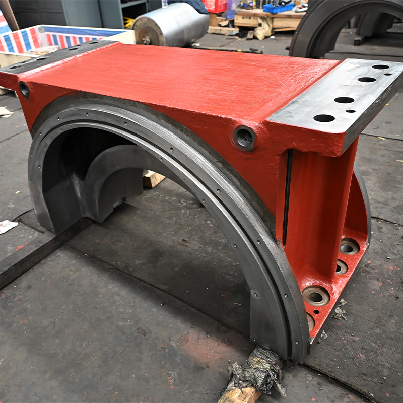
Every bearing selection process begins by analyzing the specific vessel duty cycle. A merchant marine ship operates entirely differently than a naval vessel or a tugboat. Engineers must understand these profiles to specify the correct materials and lubrication systems.
Merchant marine vessels generally run at continuous, steady speeds. They travel long distances across deep waters. This steady-state operation strongly favors hydrodynamic lubrication. The shaft RPM remains high enough to sustain a continuous fluid film. Consequently, bearing wear remains minimal over long voyages.
Workboats, ferries, and naval vessels face a much harsher reality. They experience frequent stop-and-start operations. They endure high impact loads during towing or combat maneuvers. Operating in shallow or coastal waters introduces sand and silt into the system. These frequent starts drop the shaft speed below the threshold for hydrodynamic lift. The bearing enters a boundary lubrication phase where physical contact occurs. You must select materials capable of surviving these abrasive and high-friction conditions.
You cannot isolate the bearing from the rest of the drivetrain. It must integrate seamlessly with all marine propulsion system parts. The sterntube houses the bearing and dictates the maximum allowable dimensions. Forward and aft seals protect the system from contamination and prevent fluid leakage. External struts support the shaft on multi-shaft vessels. The propeller itself dictates the overhung weight and dynamic forces transferred to the aft-most bearing. Changing one component alters the load distribution across the entire system.
Understanding how bearings fail helps you choose better materials. Edge loading is a prevalent issue. It occurs when shaft deflection concentrates extreme pressure on the outer edges of the bearing. This localized stress quickly destroys the bearing material. Abrasive wear happens when suspended solids get trapped in the clearance. The debris acts like sandpaper against the shaft liner. Galvanic corrosion presents another major threat. Dissimilar metals submerged in seawater create an electrical current. This current degrades the bearing housing or the shaft itself. You must factor these risks into your baseline material selection.
The marine industry relies on two primary lubrication methods. You must choose between oil and water based on performance needs and environmental regulations. Both systems utilize fluid dynamics, but they operate under entirely different constraints.
A Propeller Shaft Journal Bearing often relies on oil lubrication. This mechanism creates a highly stable hydrodynamic oil film between the rotating shaft and the stationary bearing. Engineers typically specify white metal or babbitt alloys for these applications.
The advantages of oil systems are substantial. They offer exceptional load-carrying capacity. They generate extremely low friction at low operating speeds. The thick oil film protects the shaft from metal-to-metal contact even during heavy maneuvers. However, the risks are equally significant. If the aft sterntube seal fails, the system loses its oil. This leads to catastrophic bearing failure in minutes. Furthermore, regulatory bodies heavily scrutinize oil discharges. The EPA and international maritime laws impose strict penalties for oil leaks into the ocean.
Water-lubricated configurations use seawater as the primary fluid. These systems typically utilize elastomeric (rubber) materials or advanced polymer composites. Often referred to as cutless bearings, they allow water to flow through internal grooves.
These systems eliminate pollution risks. They fully comply with the EPA Vessel General Permit (VGP) and the Polar Code. They also simplify the sealing arrangements because minor water leakage into the bilge is manageable. The downsides relate primarily to low-speed operations. During start-up, water lacks the viscosity to immediately separate the shaft from the bearing. The system experiences higher friction during this boundary lubrication phase. Additionally, poor water quality filled with silt or sand can accelerate wear rates if the bearing lacks proper flushing mechanisms.
Table 1: Technical Comparison of Lubrication Systems
| Feature | Oil-Lubricated (Babbitt) | Water-Lubricated (Composite/Elastomer) |
|---|---|---|
| Primary Lubricant | High-viscosity marine oil | Surrounding seawater |
| Load Capacity | Extremely high | Moderate to high |
| Environmental Risk | High (potential for ocean discharge) | Zero (environmentally benign) |
| Seal Complexity | Complex (requires forward and aft seals) | Simple (often requires only a forward seal) |
| Abrasive Tolerance | Low (requires completely clean oil) | High (grooves flush out debris) |
Specifying a bearing requires precise mathematical calculations. You cannot simply guess the dimensions. Proper sizing dictates performance. Material selection dictates durability. Clearance specifications dictate the thermal safety margins.
Engineers size bearings using the Length-to-Diameter (L/D) ratio. This standard metric divides the overall length of the bearing by its internal diameter. Traditional designs often featured L/D ratios of 4:1. Modern engineering prefers shorter ratios, often between 1.5:1 and 2:1. Over-sizing a bearing increases the initial material weight and adds unnecessary friction drag. It also makes alignment much more difficult. Conversely, under-sizing the bearing is dangerous. A bearing that is too short cannot distribute the radial load. The extreme pressure will collapse the hydrodynamic film, leading to immediate failure.
Running clearance defines the physical gap between the shaft outer diameter and the bearing inner diameter. You must strike a critical balance here. If the clearance is too tight, you risk thermal expansion binding. As the shaft and bearing heat up during operation, they expand. Without enough clearance, the bearing seizes the shaft. If the clearance is too loose, the fluid film becomes unstable. The shaft will bounce inside the housing. This induces severe vibration, edge loading, and uneven wear patterns across the bearing surface.
Material properties ultimately determine how the system handles stress and contamination. You must match the material to the operational profile.
Elastomeric and Rubber Materials: Rubber bearings excel at absorbing shock and vibration. They flex slightly under load, accommodating minor misalignments. They are highly tolerant of abrasives. Hard particles compress into the rubber and wash out through the water grooves, protecting the metal shaft.
Thermosetting Resins and Composites: These advanced polymers offer high load capacities similar to metal. They possess extremely low friction coefficients. However, they are rigid. They require precise machining and highly accurate alignment. They do not forgive installation errors.
Metallic and Babbitt Alloys: These are the standard for heavy journal applications. They handle massive, steady loads perfectly. They rely strictly on a continuous, clean oil supply. Any particulate contamination will score the soft white metal surface and destroy the bearing.
A bearing specification is only as good as its installation. You can purchase the most advanced composite material in the world, but it will fail rapidly if installed incorrectly. Proper marine shaft alignment ensures the load distributes evenly across the entire length of the bearing.
Misalignment is the primary cause of premature bearing failure. Shafts are not perfectly rigid. They bend under their own weight. They bend under the thrust forces generated by the propeller. If the bearing housing does not align with the natural curve of the shaft, the shaft will press hard against one end of the bearing. This edge loading destroys the fluid film and tears the bearing material apart.
Shaft deflection under load fundamentally changes the contact patch. The point of highest pressure shifts dynamically as the vessel maneuvers. To combat this, naval architects increasingly focus on optimizing strut layouts. The current engineering trend favors fewer struts. Eliminating unnecessary intermediate struts simplifies the alignment process. It allows the shaft to form a natural elastic curve. Fewer struts also improve the wake field flowing into the propeller, reducing cavitation and hydrodynamic vibrations.
You must verify alignment mathematically and physically during the installation phase. Shipyards use several standardized practices.
Optical and Laser Alignment: Engineers shoot a laser through the center of the bearing housings to establish a perfect geometric line. This ensures the bored holes are concentric before installing the bearing shells.
Strain Gauge Methods: Technicians attach strain gauges to the shaft. They rotate the shaft and measure the bending stress. High stress indicates the shaft is bending forcefully to enter a misaligned bearing.
Jack-Up Tests: This is the ultimate verification of bearing load. Technicians place a hydraulic jack under the shaft adjacent to the bearing. They lift the shaft slightly and measure the required force. This confirms the exact weight resting on that specific bearing.
Finalizing a bearing specification requires a structured decision process. You must evaluate the practical feasibility of installation and the long-term operational demands. This engineering assessment prevents costly retrofitting mistakes.
Selecting a system for a new ship offers total freedom. The naval architect designs the stern tube and strut structures to accommodate the chosen bearing. Retrofitting an existing hull presents severe engineering difficulties. Converting a vessel from an oil-lubricated system to a water-lubricated system requires major structural modifications. You must remove the aft oil seals. You must often bore out the existing sterntube to accept a larger composite bearing housing. You also have to install dedicated water quality packages to filter the seawater before it enters the bearing. These structural constraints often dictate the final selection for older vessels.
Use a clear engineering matrix to narrow your choices. Ask yourself specific operational questions.
Do you require maximum load capability in a closed, highly controlled system? If your vessel operates continuously in deep waters with massive propulsion forces, lean toward white metal journal bearings. Ensure you specify redundant oil circulation pumps.
Do you prioritize environmental compliance and abrasive tolerance? If the vessel operates in shallow coastal waters or faces strict emission regulations, lean toward water-lubricated composites or rubber cutless bearings. These materials handle silt and remove regulatory risks.
Once you determine the correct size, material, and lubrication type, take actionable steps. Draft a precise Request for Quotation (RFQ). Include your required L/D ratios, exact shaft dimensions, and specific duty cycle. Specify that the bearing must carry approvals from major class societies like ABS, DNV, or Lloyd's Register. Finally, consult directly with propulsion engineers to verify your thermal expansion calculations before placing the final order.
Choosing the correct propeller shaft bearing secures the reliability of your entire vessel. You must build your evaluation framework on solid engineering principles. First, define the operational profile. High-speed, continuous loads favor different lubrication methods than frequent stop-and-start operations. Second, prioritize accurate sizing. Correct L/D ratios and clearances maintain the critical fluid film. Third, demand precise alignment. No bearing survives edge loading caused by an improperly aligned shaft.
Moving forward, prioritize verifiable testing data over generalized marketing claims. Demand hydrodynamic test results and certified material wear rates from the manufacturer. By integrating the bearing seamlessly with the surrounding propulsion components, you maximize operational lifespan. Apply this structured assessment to eliminate guesswork and protect your maritime assets from premature failures.
A: You determine correct clearance by following strict OEM specifications. Engineers calculate this using the shaft diameter, typically allowing 0.001 to 0.002 inches of clearance per inch of shaft diameter. You must also factor in the thermal expansion properties and water-swelling rates of the specific bearing material.
A: A water-lubricated cutless bearing generally lasts between 5 to 10 years. However, this lifespan heavily depends on the operating environment. Vessels running in clean, deep waters achieve longer lifespans. Operating constantly in shallow, abrasive, sand-filled waters will significantly accelerate wear and reduce this timeframe.
A: Yes, conversion is possible, but it requires significant engineering. You must remove the existing oil seals and install specialized forward water seals. You must also calculate new bearing carrier dimensions and apply a highly durable anti-corrosion coating to protect the previously oil-soaked steel shaft from seawater exposure.


