
Views: 0 Author: Site Editor Publish Time: 2026-08-14 Origin: Site
A massive engineering challenge exists in modern power generation facilities. We constantly face a critical discrepancy between static maintenance states and dynamic operating conditions. Turbines sit perfectly still at ambient temperatures during repairs. However, they expand dramatically under immense thermal loads during operation. This thermal expansion shifts machine centerlines significantly.
Miscalculating thermal growth steam turbine shaft alignment brings severe consequences. It leads directly to catastrophic bearing failures. You compromise overall plant efficiency. Unplanned outages become unavoidable. Poor alignment introduces immense physical stress across the entire drive train.
This article guides reliability engineers and plant managers directly. We help you evaluate modern compensation strategies effectively. You will learn to verify OEM targets against real-world operational data. We also explore how to select the right alignment verification methodology. Mastering these specific steps ensures your rotating equipment survives the harsh realities of thermal expansion.
Cold alignment is only the starting point: Relying strictly on static measurements without verifying dynamic thermal expansion guarantees operational misalignment.
Differential growth is non-linear: Variations across high-pressure and low-pressure sections require segmented, continuous monitoring rather than single-point estimates.
Verification extends MTBF: Implementing precise thermal compensation significantly reduces load on bearings and seals, extending the lifecycle of critical turbine components.
Tooling selection matters: Choosing between offline calculations, laser alignment systems, and continuous dynamic monitoring dictates the accuracy of your compensation targets.
When heavy machines heat up, they move predictably but forcefully. Thermal expansion alters the established centerlines of coupled machines. A perfect cold alignment easily transforms into a destructive hot misalignment. The center of rotation shifts both vertically and horizontally. This shift introduces massive lateral forces. These forces attack every component along the driveline relentlessly.
Consider the direct impact on the Steam Turbine Rotor Shaft. Off-center rotational forces cause severe physical stress immediately. You will observe increased vibration levels quickly on your monitors. The shaft undergoes continuous cyclic deflection during operation. Over time, this constant bending introduces a very high risk of fatigue failure. The shaft literally flexes millions of times per week. Such stress shortens the operational lifespan drastically.
Misalignment also wreaks havoc on specialized bearings. It aggressively degrades the critical hydrodynamic oil film inside a DIN Sliding Bearing. The heavy shaft journal pushes straight through the protective fluid layer. Metal-to-metal contact accelerates babbitt metal wear significantly. You will see elevated bearing temperatures almost immediately on your monitoring dashboards. This rapid wear permanently damages the internal bearing profile.
Secondary risks further complicate plant operations. Collateral damage to various Steam Turbine Parts inflates annual maintenance budgets. We often see severe labyrinth seal rubbing during inspections. Couplings wear out prematurely under heavy angular strain. Localized overheating degrades overall structural integrity. These cascading mechanical failures greatly increase the risk of forced outages. Forced outages destroy production schedules completely and ruin facility profitability.
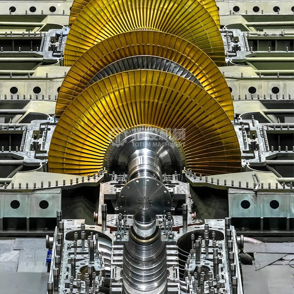
Steam temperatures vary drastically across a modern turbine train. Extreme heat hits the main inlet valves first. Temperatures drop significantly as steam nears the massive exhaust section. These steep temperature gradients cause highly uneven thermal expansion. The entire machine twists and bows slightly during normal operation.
The HP/IP/LP Turbine Casing reacts uniquely to this intense heat. High-pressure (HP) sections expand rapidly due to massive inlet temperatures. Intermediate-pressure (IP) and low-pressure (LP) casings grow at completely different rates. Differential thermal growth makes establishing accurate alignment targets highly complex. You cannot apply a single expansion value across the entire machine safely.
You must distinguish between outer casing distortion and internal rotor growth. The massive outer casing expands differently than the lighter internal rotor. The rotor heats up much faster during initial startup phases. Foundation movement exacerbates these alignment shifts over time. Pipe strain pushes or pulls the entire turbine assembly. These external forces combine aggressively.
Maintenance teams must evaluate specific criteria before measuring anything. They should document ambient temperatures carefully during the cold alignment phase. Operating loads must be recorded precisely for future comparison. Note the specific foundation types under each individual casing section. Building an accurate thermal profile requires capturing all these details. You can then select the most appropriate measurement tool for your facility confidently.
Original Equipment Manufacturers (OEMs) provide theoretical thermal offset targets routinely. They calculate these valuable numbers during the initial engineering phase. However, these theoretical numbers have strict limits in aging power plants.
OEM data often fails to account for site-specific variables entirely. Machinery ages predictably over long periods. Foundations settle unevenly over decades of heavy vibration. Plant upgrades often modify existing steam piping routes. These piping modifications introduce completely new pipe strain. Real-world conditions rarely match pristine factory assumptions. Relying blindly on OEM manuals invites serious mechanical trouble.
Thermal growth is not the only variable affecting alignment. Dynamic positional change complicates matters much further. Dynamic forces shift the machine centerline actively during operation. Heavy torque twists the massive casings. Fluid pressure variations push internal components around constantly. Vacuum forces pull the large exhaust ends downward aggressively. All these forces alter the true running position.
We highly recommend using a clear decision framework. You need to know exactly when to trust OEM specifications.
Trust OEM cold alignment targets when: The machine is brand new. The concrete foundation is perfectly pristine. All connected piping matches original blueprints exactly.
Invest in empirical targets when: You experience repeat, unexplained bearing failures. The foundation shows visible signs of settling. You recently modified steam or cooling piping structures.
Conduct new verifications when: You change flexible coupling types. Operating temperatures shift due to major process changes. You experience severe seasonal temperature extremes on the turbine deck.
Live-measured thermal compensation targets always yield much better long-term reliability.
Engineers use several methods to compensate for thermal movement. Each technical category offers distinct advantages and specific limitations. Choosing correctly dictates your ultimate alignment success.
Many maintenance teams still rely on traditional mathematical formulas. They multiply the material coefficient of thermal expansion by length and temperature change. This straightforward approach works well for simple pump setups. However, it fails completely in complex, multi-casing turbine trains. Mathematical calculations cannot predict random foundation shifting. They ignore dynamic pipe strain entirely. You get a theoretical guess at best.
Modern laser shaft alignment systems offer much better accuracy. Users input calculated thermal growth values directly into the digital software. The laser tool then calculates precise cold alignment offsets automatically. This method ensures the machine starts in the exact prescribed offset position. The limitation remains the baseline quality of the inputted thermal data. If your math is wrong, the laser simply perfects a bad alignment target.
Advanced monitoring systems currently provide the highest possible accuracy. Engineers use specialized laser trackers or water-cooled optical sensors. These rugged devices measure live positional changes continuously. They track physical movement perfectly from cold start to full operating temperature. This empirical data completely eliminates engineering guesswork. You see exactly how the complex machine behaves dynamically under load.
Review the technical comparison chart below carefully. It maps these distinct methodologies based on scalability, accuracy limits, necessary downtime, and required operator expertise.
Thermal Compensation Methodologies Comparison
| Methodology | Scalability | Accuracy Limits | Necessary Downtime | Required Operator Expertise |
|---|---|---|---|---|
| Mathematical Calculation | Low | Theoretical estimates only | Minimal | Moderate (Basic engineering math) |
| Laser Alignment Tooling | Medium | High for static offset positioning | Moderate | High (Laser operation training) |
| Dynamic Monitoring | High | Live, empirical positional precision | High (Initial setup phase) | Advanced (Specialized optical sensors) |
Successfully executing thermal growth steam turbine shaft alignment requires strict discipline. You must follow a rigid procedural roadmap. Skipping essential steps invites catastrophic mechanical disaster.
You must eliminate soft foot conditions completely first. Check all coupling runout tolerances rigorously using dial indicators. Ensure you mitigate all pipe strain before turning on any laser. Attempting thermal compensation on a strained machine simply wastes valuable time. The equipment base must remain perfectly stable. Clean all mounting surfaces thoroughly. Remove all rust, dirt, and debris completely.
Follow a strict step-by-step logic for applying offsets effectively.
Gather your calculated or field-measured thermal offset data accurately.
Enter these specific numerical values into your laser alignment system interface.
Intentionally misalign the cold machine exactly according to the prescribed offsets.
Tighten all machinery hold-down bolts evenly using a calibrated torque wrench.
Re-measure the final cold state to confirm the exact target position.
The mechanical job continues long after equipment startup. You must validate the thermal growth compensation carefully. Measure vibration signatures once the turbine reaches full operating load. Monitor bearing temperatures closely across all internal zones. A sudden temperature spike indicates poor compensation immediately. Smooth, flat vibration trends prove your thermal offsets were highly accurate. Document these final baseline readings for future reference.
You may need highly specialized third-party alignment services eventually. Choose your equipment vendors very carefully. Look for strict, documented compliance to recognized ISO alignment standards. Ask for verifiable case studies in similar power generation plants. They must provide comprehensive, transparent reporting capabilities. A good vendor always explains their measurement process clearly. They should welcome your engineering questions actively.
Mastering thermal growth in steam turbine shaft alignment remains absolutely mandatory today. It ensures true plant reliability consistently across all operations. It is never merely an optional maintenance upgrade. We see the direct benefits of precision alignment daily in successful plants.
Transitioning away from theoretical guesses transforms your maintenance program completely. Empirical dynamic measurement genuinely secures long-term asset longevity. You reduce catastrophic bearing failures dramatically. Your annual maintenance budget becomes far more predictable over time.
Take decisive action today before minor problems escalate rapidly. Schedule a comprehensive alignment audit for your next planned outage. Request a live demo of advanced dynamic measurement tools from leading vendors. Alternatively, download a technical whitepaper on turbine casing expansion limits. Secure your critical rotating machinery now.
A: Thermal growth varies significantly by machine size and operating temperature. Small expansions range from mere thousandths of an inch. Large turbines experience substantial fractions of an inch. This wide variance requires precise empirical measurement rather than rough estimations.
A: OEM targets serve as excellent baselines initially. However, they cannot predict everything. Real-world factors heavily influence alignment over time. Foundation shifts and acquired pipe strain change how a machine moves. Site-specific verification remains essential for true reliability.
A: Thermal growth refers strictly to temperature-induced material expansion. Dynamic movement encompasses all operational forces acting on the machine. Torque, fluid pressure changes, and vacuum forces shift the machine’s centerline while running. Both factors contribute heavily to hot operational misalignment.
A: You should verify targets after any major mechanical event. Major overhauls require new verifications immediately. Piping modifications or foundation repairs also alter thermal behavior significantly. Do not assume historical targets remain static over the lifespan of the equipment.


