


| Quantity: | |
|---|---|
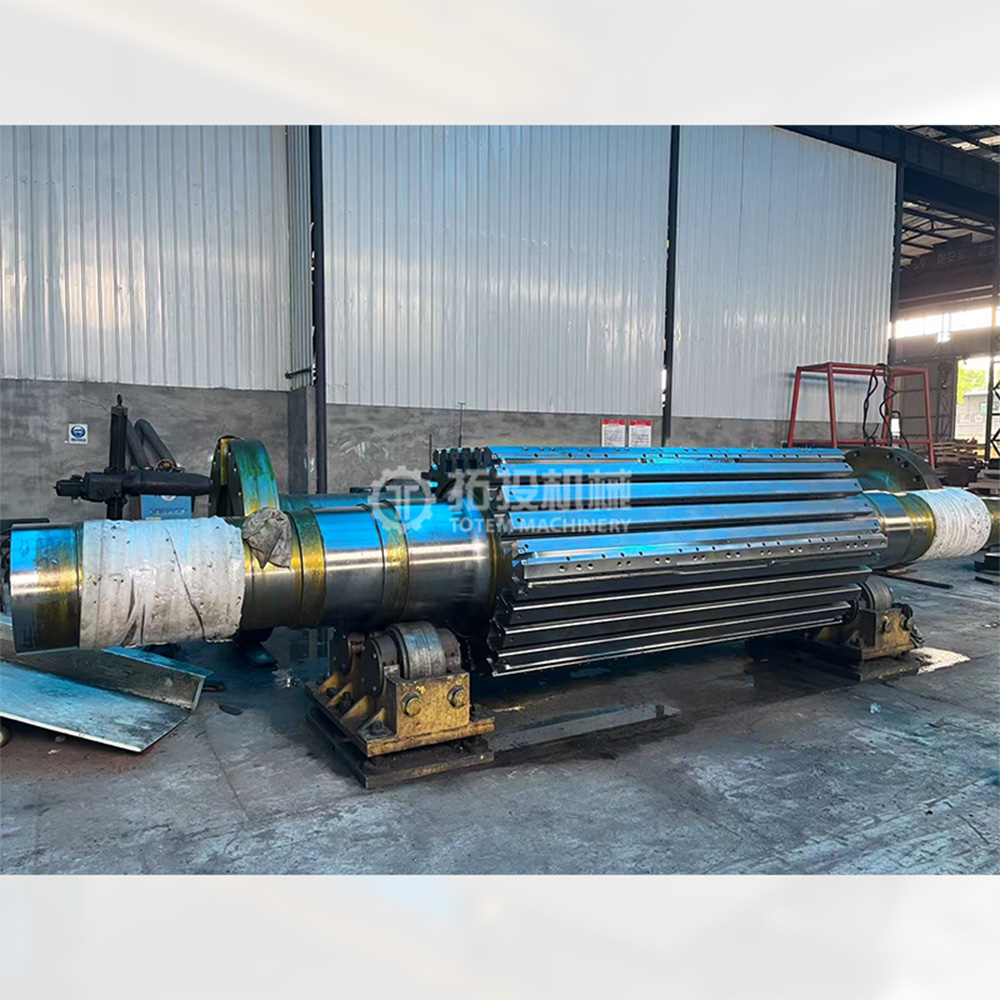
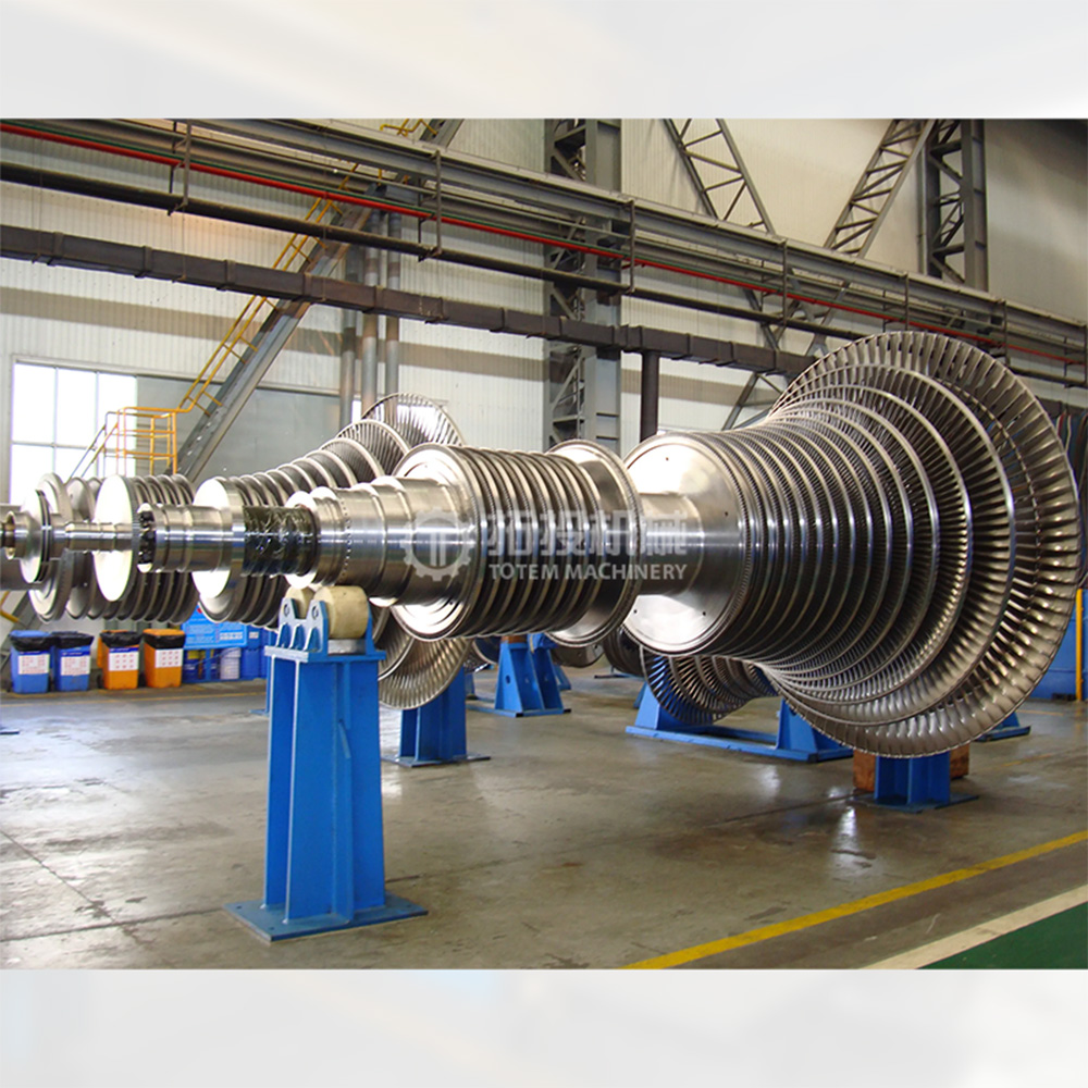
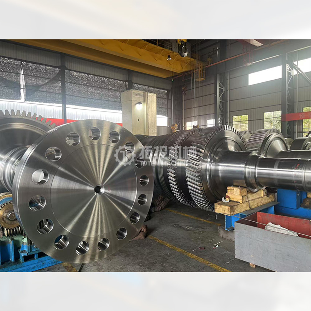
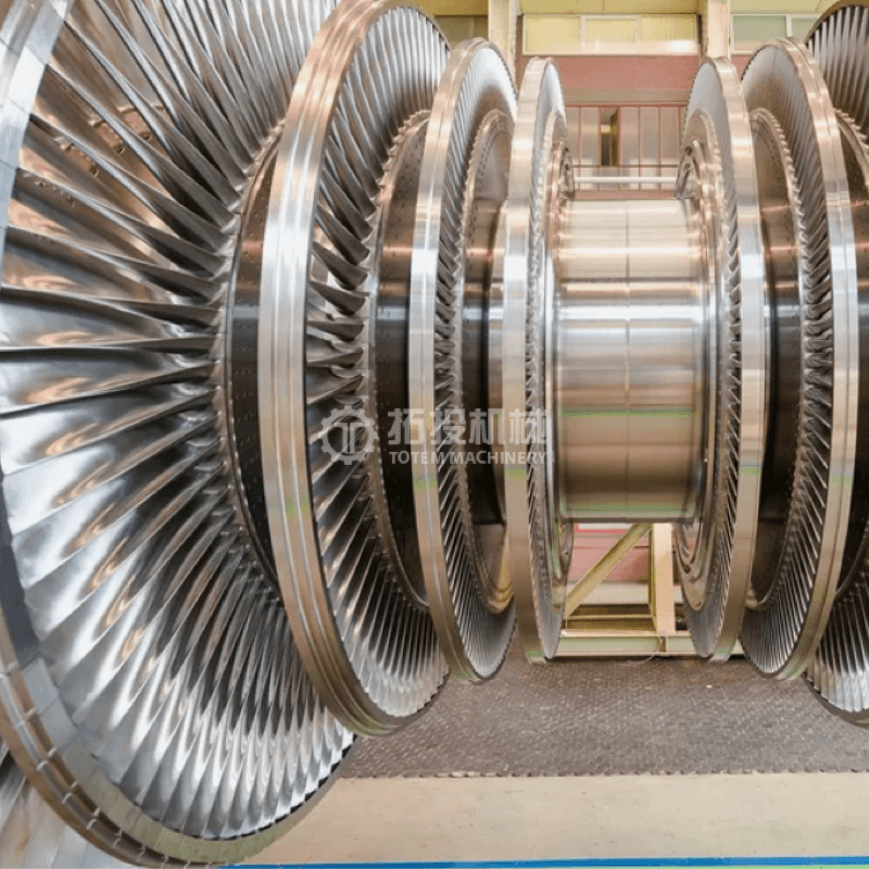
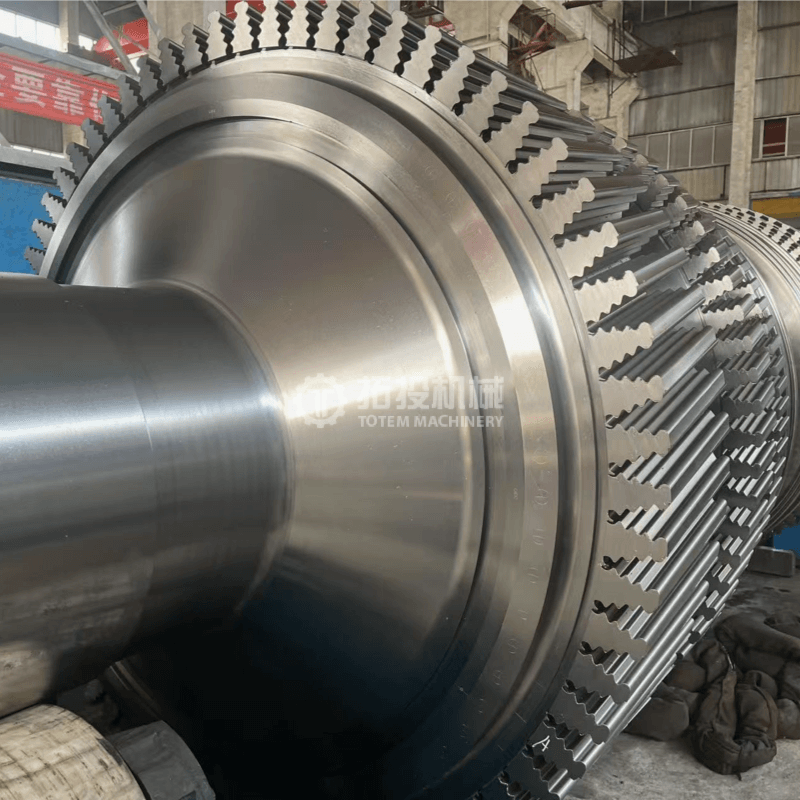
The high-pressure (HP), intermediate-pressure (IP), and low-pressure (LP) rotor shafts are the most critical load-bearing and power transmission components within industrial and utility steam turbine systems. Operating at the heart of the turbine, these forged rotor shafts perform essential functions, including transmitting immense rotational torque, securely supporting moving blades, and maintaining a stable connection to the generator or driven equipment. The structural integrity, dimensional stability, and material reliability of these shafts directly determine the operational safety, overall thermal efficiency, and long-term service life of the entire steam turbine unit. For engineering projects and power generation facilities, selecting properly manufactured rotor shafts is vital to minimizing maintenance downtime and mitigating operational risks under demanding continuous loads.
To ensure optimal performance across different thermal and mechanical stress zones, we implement strict material selection protocols tailored to specific operational environments. For HP and IP rotor shafts, which are exposed to extreme thermal conditions, we utilize premium alloy steel forgings, specifically Cr-Mo-V series or Ni-Cr-Mo series steels. These advanced alloy compositions provide exceptional high-temperature strength, superior creep resistance, and excellent thermal fatigue endurance. This ensures the shafts maintain their mechanical properties and dimensional accuracy even under prolonged exposure to high-temperature, high-pressure, and high-speed steam flows, significantly reducing the risk of thermal deformation.
Conversely, LP rotor shafts operate under different mechanical demands, primarily enduring large rotational diameters, massive torque transmission, and complex alternating stresses. For these components, we utilize high-strength low-alloy steels or specialized low-pressure rotor steels. This targeted material strategy delivers an optimal balance of structural strength, impact toughness, and crucial resistance to stress corrosion cracking, making them highly reliable for handling high-volume, low-pressure steam environments without compromising structural integrity over years of continuous operation.
 |  |  |
 |  |  |
Meeting stringent international specifications is a fundamental requirement for power generation equipment. Our steam turbine rotor shafts are meticulously manufactured in full compliance with established global standards, including GB, DIN, and ISO specifications, depending on specific project requirements. Every forged shaft is delivered with comprehensive quality documentation, material certificates, and detailed inspection reports to ensure full traceability and support your quality assurance processes.
Beyond standard manufacturing, we provide comprehensive customized engineering support. Based on your specific turbine unit parameters, operational conditions, and performance targets, our engineering team can offer valuable insights for structural optimization, material selection guidance, and manufacturing feasibility analysis. This collaborative approach helps procurement teams and engineers optimize their equipment designs, ensuring the final rotor shaft perfectly matches the intended application while controlling overall project costs.
Backed by mature forging expertise and a rigorous quality management system, our HP, IP, and LP steam turbine rotor shafts deliver the high strength, exceptional reliability, and extended service life required for modern power generation. They offer excellent engineering adaptability, making them the dependable choice for a wide variety of demanding steam turbine projects and heavy industrial applications.
The manufacturing of our high-pressure alloy steel steam turbine rotor shafts relies on a highly controlled and sophisticated machining process. Before any cutting tool touches the metal, the key forgings for rotor shafts undergo stringent controls in smelting, forging, and heat treatment. These foundational steps are meticulously executed to ensure a uniform microstructure and exceptional internal denseness. By eliminating internal voids and achieving structural homogeneity during the early stages, we provide a highly stable foundation for precision machining. This strict preliminary control significantly reduces the risk of material deformation or stress relief warping during subsequent heavy material removal, ensuring dimensional stability throughout the production cycle.
Once the foundational forging is prepared, the rotor shaft enters our heavy-duty machining facility. The massive physical dimensions and complex geometry of steam turbine rotors require specialized equipment. We utilize large-scale CNC (Computer Numerical Control) lathes, heavy-duty CNC grinders, and specialized finishing equipment designed specifically for large industrial components.
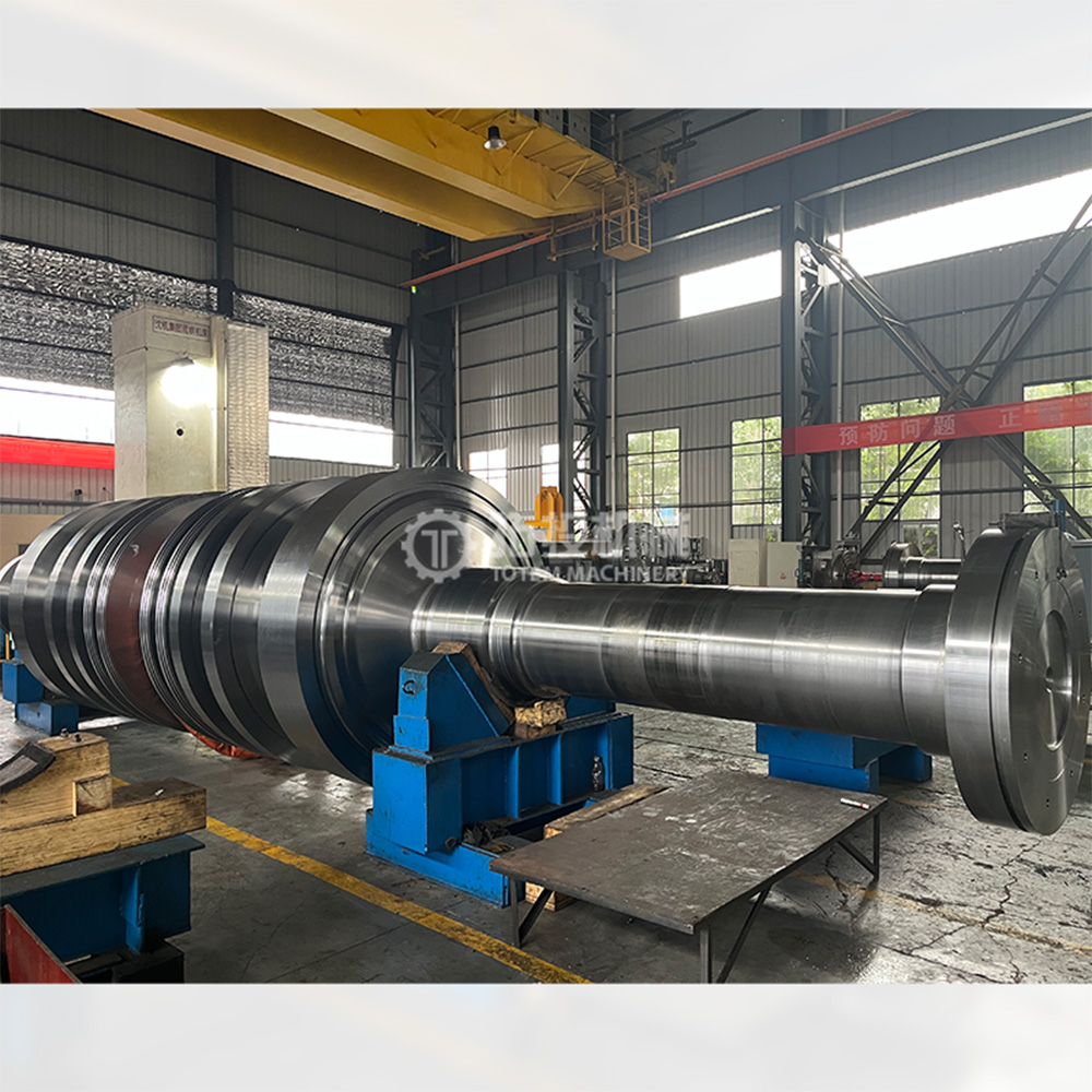
During the machining phase, extreme attention is given to critical functional areas of the rotor shaft. The journal areas, which bear the immense weight of the rotating assembly and interface with the hydrodynamic bearings, are machined to exact tolerances to ensure smooth rotation. The sealing zones are precisely cut to maintain tight clearances, which is vital for preventing high-pressure steam leakage and maintaining turbine efficiency. Furthermore, the disc locating surfaces and coupling sections are processed with absolute precision. The coupling sections must align accurately with the generator rotor, demanding flawless execution to ensure stable power transmission without introducing eccentric loads.
As illustrated in our finish turning operations above, the transition from rough machining to final finishing is carefully monitored. Finish turning is a critical phase where the rotor shaft approaches its final geometric specifications. During this stage, our skilled operators and advanced CNC systems work in tandem to remove the remaining material with high precision. This step requires optimized cutting speeds, precise feed rates, and specialized tooling to prevent work hardening and minimize residual surface stresses, preparing the shaft for final grinding.
The ultimate goal of our comprehensive machining process is the strict control over key geometric tolerances, specifically roundness, coaxiality, and surface roughness. In high-speed rotating equipment like steam turbines, even microscopic deviations can lead to severe operational issues. Strict control over roundness ensures that the shaft rotates evenly within its bearings, minimizing friction and mechanical wear. Coaxiality is paramount; all machined diameters along the entire length of the massive shaft must share an exact common centerline. This geometric accuracy is essential for achieving optimal dynamic balance. Without precise coaxiality, the rotor would experience severe vibrations at high rotational speeds, compromising the shafting stability and potentially leading to equipment downtime.
Additionally, surface roughness is strictly controlled through advanced turning and subsequent grinding processes. A superior surface finish in the journal and sealing areas reduces wear, extends the lifespan of mating components, and enhances the overall operational safety of the steam turbine system. By maintaining these rigorous machining standards, we ensure that every rotor shaft delivered is fully capable of withstanding the demanding dynamic forces present in modern power generation environments.
Finish Turning
Finish Turning
Finish Turning
Product Inspection
All rotor shafts from our company are subject to rigorous quality control procedures. Key manufacturing stages involve non-destructive testing such as Ultrasonic Testing (UT) and Magnetic Particle Testing (MT), along with necessary dimensional and performance inspections. Upon completion of manufacturing, run-out test and roughness test are conducted to guarantee smooth, safe, and reliable rotor operation.
Run-Out Test
Roughness Test


