Please Choose Your Language
Views: 0 Author: Site Editor Publish Time: 2026-10-28 Origin: Site
A steam turbine can show a pronounced vibration response during acceleration even when its shaft is strong enough to transmit the required torque. The missing consideration is rotor dynamics: how the turbine shaft, attached masses, bearings, and supports move together. Critical speed identifies a speed region where an excitation can interact strongly with a lateral rotor mode. It does not automatically identify a failure speed or a maximum operating speed. Understanding the distinction helps engineers assess operating ranges, investigate vibration, and evaluate replacement components. The essential inputs are system stiffness, mass distribution, bearing behavior, excitation, and damping.
A lateral critical speed is a rotational speed associated with a resonant response of the rotor-bearing system to a particular excitation. For synchronous unbalance excitation, it is commonly identified where the rotational frequency meets a relevant lateral whirl-mode frequency, interpreted in a consistent reference frame.
The turbine shaft can have several lateral bending modes, each with its own deformation pattern. As rotational speed changes, gyroscopic effects and speed-dependent support properties can change the modal frequencies. A real rotor therefore cannot always be represented by one fixed natural frequency and one critical speed.
Response severity depends on how strongly the excitation couples into the mode, the available damping, and the measurement location. A predicted frequency crossing identifies a potential resonance condition; forced-response analysis establishes the expected amplitude and phase behavior. A damped response peak can occur at a different speed from an idealized undamped crossing.
This discussion concerns lateral rotor behavior. Torsional modes involve relative angular motion along the shaft train, while blade modes involve different structural motion. Those require their own excitation and resonance assessments. Treating every vibration peak as the same kind of critical speed can send an investigation in the wrong direction.
Higher effective bending stiffness tends to raise a mode's natural frequency when mass and support conditions remain comparable. Greater effective modal mass tends to lower it. For a simplified single-mode representation, the relationship is fn ≈ (1/2π)√(keff/meff).
The terms are modal quantities, not simply total rotor weight and one catalog stiffness value. Where material sits matters. A heavy disk near a region of high modal displacement can influence one mode more strongly than the same added mass near a node. Coupling hubs, blade rows, collars, and other rotor features all contribute to the modeled mass and inertia distribution.
For a solid circular section, the second moment of area for bending is I = πd4/64. This differs from the polar second moment used in torsion. Increasing diameter can strongly increase bending stiffness, but it also adds mass and changes rotary inertia. The net modal effect depends on where the turbine shaft is enlarged and which mode is being considered.
An ideal uniform, simply supported beam gives useful intuition: its bending frequencies scale with √[EI/(ρA)]/L². For fixed material and geometrically uniform solid sections, that suggests a diameter-to-length-squared trend. Actual stepped rotors have concentrated masses, flexible supports, gyroscopic effects, and potentially important shear deformation, so this trend is not a turbine critical-speed prediction.
Material substitution also needs care. A stronger steel can improve a stress margin without proportionally increasing elastic modulus. A strength upgrade should not be assumed to move a resonance away from an operating range.
Bearings and their supporting structures define how the turbine shaft is restrained. Bearing span changes bending flexibility and mode shapes, while bearing stiffness and damping affect both modal behavior and vibration response.
A longer unsupported span generally makes a comparable shaft more flexible. Moving a bearing, however, also changes overhangs, reactions, and the relationship between heavy rotor sections and supports. The resulting change in a particular mode must be calculated using the revised geometry rather than inferred from span alone.
A hydrodynamic journal bearing supports the rotor through an oil film. Its effective stiffness and damping depend on operating conditions, including rotational speed and bearing load. Clearance, lubricant viscosity, and temperature also belong in the bearing assessment. A fixed support assumption can miss important behavior when the actual oil-film support is flexible.
Engineers commonly represent small motions around the journal equilibrium position using direct and cross-coupled stiffness and damping coefficients. This linear approximation has limits: large excursions or strongly nonlinear conditions may require a more detailed model. Useful damping can reduce resonance amplification, but cross-coupled forces can also affect stability.
The housing, pedestal, and foundation can add further flexibility. Increasing bearing stiffness may have limited benefit if the structure beneath it remains compliant. Direction-dependent support behavior can also separate or reshape lateral modes. The steam turbine bearing selection therefore needs to reflect the rotor and operating conditions, not just the bearing bore size.
Operating speed describes shaft rotation; excitation frequency describes a forcing cycle; critical speed describes a system resonance condition. They are related, but they are not interchangeable.
For synchronous excitation, frequency in hertz is n/60 when speed n is in rpm. At 3,000 rpm, the 1× excitation frequency is 50 Hz. That conversion alone says nothing about whether a particular turbine shaft has a resonance at 3,000 rpm.
Unbalance produces synchronous forcing. In a simple representation its force amplitude increases with unbalance magnitude and angular speed squared. The resulting displacement still depends on the rotor's frequency response. Thermal bow can alter effective eccentricity, while misalignment, rubbing, and fluid forces can create different response signatures. A dominant 1× component is useful evidence, not a complete diagnosis.
Acceleration and deceleration sweep excitation through different frequencies. Some turbines are designed to operate above a lower lateral critical speed and pass through its response region during a controlled transition. The permissible procedure, vibration limits, and speed restrictions must come from the machine-specific engineering assessment and operating instructions; there is no universal crossing rate.
Separation from synchronous critical speeds is also not a complete stability assessment. Fluid-induced subsynchronous behavior can occur through a different mechanism. Engineers should distinguish an externally forced resonance from a self-excited instability before choosing corrective action.
Engineers combine rotor modeling, modal calculations, unbalance-response analysis, stability assessment, and measured vibration. Each method answers a different question, so no single plot should carry the entire acceptance decision.
A rotor model represents the stepped turbine shaft, bores, disks, blade masses, couplings, material properties, bearings, seals where relevant, and structural supports. Finite-element methods allow engineers to assess complex geometry and calculate mode shapes over a range of rotational speeds. The model should use the applicable hot or cold condition rather than an unspecified set of room-temperature inputs.
Track mode shapes as well as frequencies. Modes can approach each other or change character with speed, and simply sorting frequencies from lowest to highest can obscure their identity. Sensitivity studies on bearing coefficients, support stiffness, and relevant clearances show whether an apparently adequate separation depends on uncertain inputs.
A Campbell diagram plots modal frequency against rotational speed. In a stationary-frame presentation, the synchronous excitation line follows f = n/60. Its intersection with a relevant modal branch flags a potential synchronous resonance. Forward and backward whirl identification and the excitation's ability to excite a mode still matter.
Conceptual diagram only: The curves above come from an idealized gyroscopic oscillator with selected illustrative parameters. They demonstrate frequency tracking and a 1× crossing; they do not represent a TOTEM product, a measured turbine, or an approved operating range. A backward-mode crossing is not automatically excited by forward synchronous unbalance in an ideal isotropic system. Real Campbell curves depend on rotor geometry, bearing coefficients, gyroscopic effects, and the selected reference frame.
Unbalance-response calculations estimate vibration amplitude and phase at specified locations for defined unbalance cases. Stability analysis examines whether perturbations decay or grow. Those results should be considered alongside frequency separation, clearance requirements, and the acceptance basis for the particular machine.
During commissioning or investigation, qualified personnel can compare modeled behavior with vibration amplitude and phase versus speed, frequency spectra, shaft orbits, bearing temperatures, and relevant operating conditions. Probe runout, sensor location, and measurement conventions need attention. A low housing reading alone does not establish that shaft motion is acceptable everywhere.
Design or replacement change | Review before acceptance | Why it matters |
|---|---|---|
Shaft diameter, bore, or coupling mass changes | Update rotor geometry, mass, inertia, and modal model | Nominal fit does not establish dynamic equivalence |
Bearing clearance or lining geometry changes | Recalculate applicable bearing coefficients and response | Support behavior may differ despite the same bearing envelope |
Support or pedestal modification | Review directional stiffness and structural modes | The support can participate in rotor motion |
New vibration peak during startup | Compare speed, phase, spectra, and operating condition | A peak alone does not identify its cause |
Operating-speed range changes | Reassess relevant crossings, response, and stability | Previous acceptance may not cover the new duty |
Manufacturing and assembly quality help realize the geometry and interfaces assumed by the rotor model. They do not independently guarantee an acceptable critical speed or vibration response.
For a turbine shaft, journal dimensions, roundness, datum-based runout, coaxial relationships, surface texture, and mass distribution deserve explicit requirements. Geometric concentricity and mass balance are different properties: a shaft that looks accurately machined can still require balance assessment. Conversely, balancing cannot correct every dimensional or assembly defect.
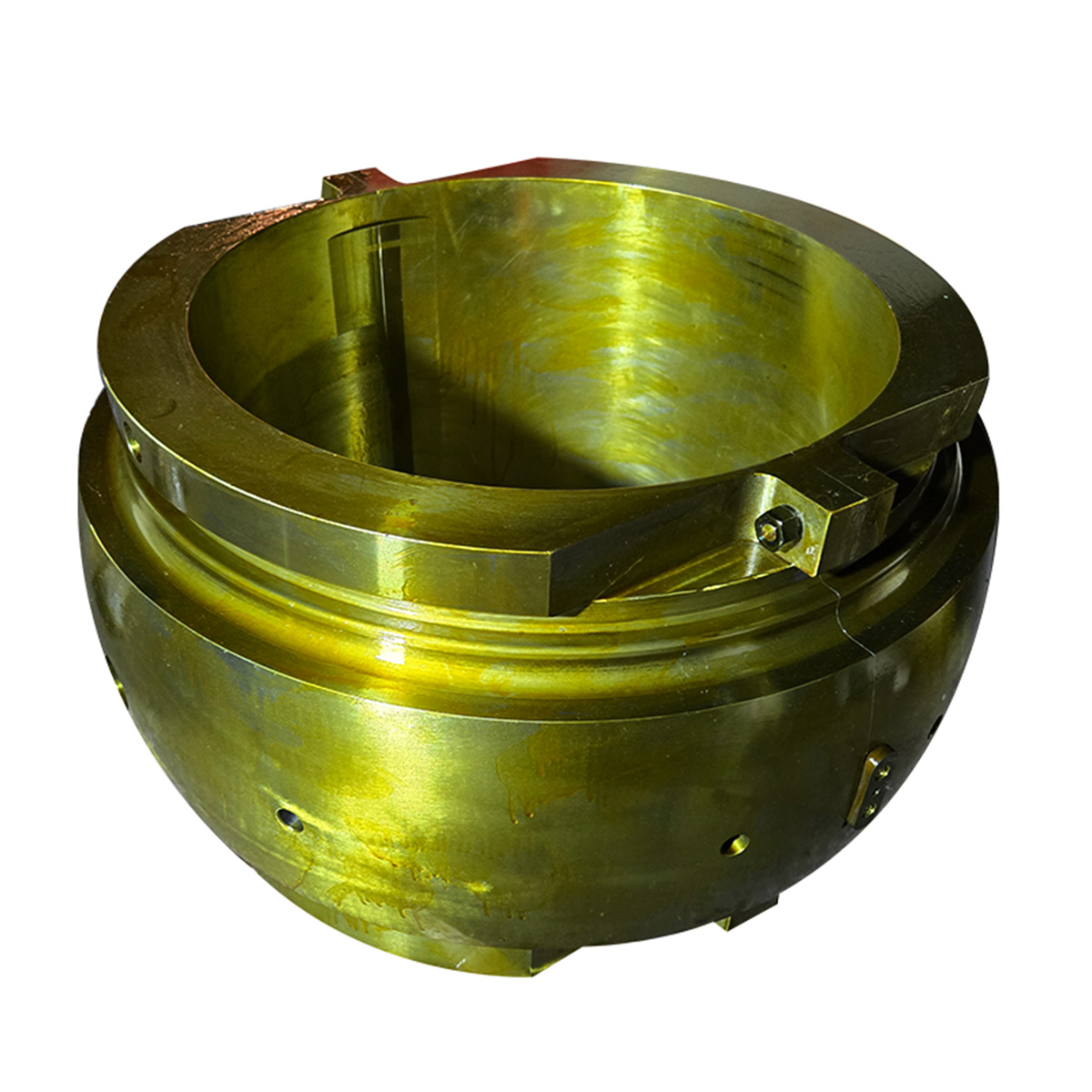
Bearing bore geometry, lining condition, fit, and assembled clearance affect how the journal is supported. TOTEM offers turbine bearing bushings with tin-based alloy lining. Component selection still requires the approved bearing design and operating basis; the lining material alone does not establish dynamic suitability.
Shanghai TOTEM Machinery Co., Ltd. provides drawing-based machining of steam turbine components, with turning, milling, grinding, and dimensional inspection capabilities. A practical handover should identify the approved drawing revision, material condition, datum scheme, inspection results, and any changes from the analyzed configuration. Requirements for balancing, assembly verification, and system testing must be assigned explicitly rather than assumed to be included in ordinary dimensional inspection.
Steam turbine critical speed is a property of the rotor, bearings, and supports acting together. Shaft stiffness and mass distribution establish part of the behavior, while oil-film properties, structural flexibility, damping, and excitation determine how the system responds. Use a Campbell diagram to identify potential crossings, then assess forced response, stability, and machine-specific separation requirements. Shanghai TOTEM Machinery Co., Ltd., a manufacturer and supplier of machined components, supports drawing-based production of shafts and bearings. Those components should conform to the approved geometry and inspection requirements, with rotor dynamic acceptance established for the complete assembled system.
The principal factors are shaft geometry and stiffness, rotor mass and inertia distribution, bearing span, bearing dynamic coefficients, support flexibility, and speed-dependent effects. Operating temperature and load can change important model inputs. Excitation and damping determine the resulting resonance response.
It often raises bending stiffness, but it also changes mass and inertia. The effect depends on the location of the change, the mode shape, and the supports. A revised rotor model is needed to quantify the change.
A longer span generally increases bending flexibility in a comparable arrangement. Moving bearings also changes overhangs, reactions, and modal shapes, so its effect on individual critical speeds must be evaluated for the actual shaft layout.
No. Critical speed concerns resonance behavior. Maximum operating speed is a machine-specific limit based on the complete mechanical, thermal, dynamic, and protection design. Some rotors operate above a lower critical speed under approved conditions.
Identify relevant critical speeds and compare them with the specified operating-speed range using the definitions and margins required by the applicable machine specification. Confirm the result with response and stability analyses. No single percentage applies to every steam turbine.