
Views: 0 Author: Site Editor Publish Time: 2026-08-05 Origin: Site
Marine shaft alignment problems rarely begin because the shaft itself suddenly moves. More often, the reference structure beneath the shaftline changes shape as cargo, ballast, buoyancy, sea state, and machinery temperature vary. A cold, dockside alignment can therefore produce different bearing reactions once the vessel is afloat, loaded, and thermally stabilized.
For hull deflection shaft alignment, the practical question is not whether the hull bends, but how each bearing support moves relative to the shaftline—and whether those movements create overload, unloading, edge contact, or localized bearing heating under real operating conditions.
A propulsion shaftline does not operate on an independent and permanently fixed geometric reference. Intermediate bearings, thrust bearings, gearbox supports, and engine foundations are attached to a hull structure that changes shape under different operating conditions.
Longitudinal weight and buoyancy distributions can produce hogging or sagging. Changes in draft, cargo position, ballast distribution, fuel consumption, and tank status can further alter the hull girder shape. Sea loads add dynamic deformation, meaning bearing offsets established in one static condition cannot automatically represent every operating condition.
For shaft alignment, the most important factor is not simply the maximum vertical hull deflection. What matters is the relative displacement and rotation between individual shaft-support locations.
If two adjacent bearing foundations move upward by almost the same amount, the local change in shaft alignment may be limited. If one support moves more than the other, however, the shaft's elastic curve must adapt between them. This can change shaft slope, bending moment, and bearing reactions.
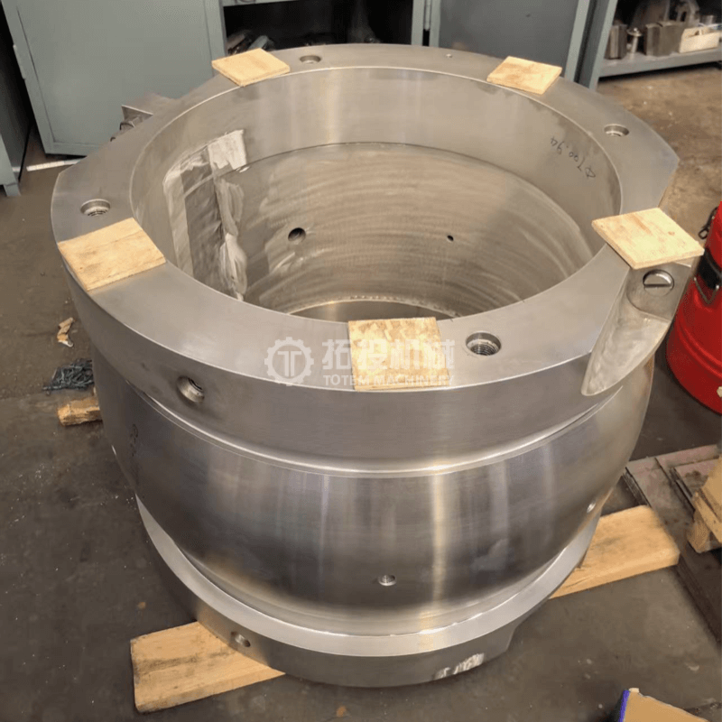
This is especially relevant around a Marine Intermediate Shaft. The intermediate shaft transmits torque between supporting bearings, so journal geometry, flange interfaces, shaft straightness, and the relationship between adjacent shaft sections all influence the installed geometry. Accurate machining establishes the intended starting condition, while hull deformation determines how that geometry is supported in service.
The alignment objective is therefore not to make the shaftline perfectly straight in one condition. Bearing offsets should create an elastic shaft curve that remains acceptable across the expected operating envelope.
A marine propulsion shaftline behaves as a continuous elastic system. Movement at one bearing support changes how load is shared by other bearings along the line.
If an intermediate bearing moves upward relative to the shaft's elastic curve, its reaction load may increase while adjacent bearings carry less load. If a support moves downward, the opposite can occur, potentially causing partial unloading and transferring additional reaction to neighboring bearings.
This means relatively small support movements can sometimes produce substantial percentage changes in an individual shaft alignment bearing load.
Bearing reaction, however, does not describe the complete bearing condition. A journal bearing carries load through a hydrodynamic pressure distribution between the shaft journal and bearing surface. Hull deformation can change the relative angle between the shaft and the bearing even when the total reaction changes only slightly.
This matters because pressure may shift toward one end of the bearing. The effective contact region becomes smaller, local pressure increases, and the oil-film safety margin can decrease. In operation, the result may appear as localized temperature rise rather than obvious whole-bearing overload.
A hydrodynamic Intermediate Shaft Bearing supports the shaft radially. Its operating condition depends on multiple interacting variables, including journal geometry, bearing clearance, lubrication, rotational speed, bearing position, and shaft-bearing attitude.
For this reason, bearing condition should be evaluated using more than a single reaction value. Relevant checks include bearing reaction, unloading tendency, shaft slope at the bearing, possible edge loading, and whether abnormal temperature repeatedly occurs under particular loading or operating conditions.
An underloaded bearing is not automatically safe either. If its reaction approaches zero, its ability to support and stabilize the shaftline is reduced, while neighboring bearings can receive additional load.
A hull deflection shaft alignment model is useful only when the analyzed conditions resemble the vessel's actual operating envelope. Cold installation is necessary for production and commissioning, but it represents only one point in the shaftline's service condition.
Draft changes, cargo distribution, ballast transfer, thermal growth, propeller loading, and sea-induced hull bending can all change the relationship between the shaft and its supporting bearings.
| Condition | Main Alignment Change | Practical Check |
|---|---|---|
| Dry dock or cold installation | Initial bearing offsets and construction reference | Establish repeatable baseline geometry |
| Afloat or ballast condition | Buoyancy changes hull-support deformation | Compare support movement and bearing reactions |
| Loaded operating draft | Cargo and tank distribution alter hull girder shape | Check critical loaded and partial-load cases |
| Hot running condition | Machinery, supports, oil, and shaft temperatures stabilize | Verify hot alignment assumptions and bearing temperatures |
| Maneuvering or severe sea condition | Propeller forces and transient hull bending increase | Check sensitive bearings and available load margins |
A vessel loading condition shaft alignment assessment should consider how weight is distributed, not simply total displacement or mean draft.
Two loading conditions may have similar displacement but produce different longitudinal bending if cargo and ballast are positioned differently. A vessel can therefore experience a more unfavorable shaftline condition at an intermediate loading state than at full load.
The critical condition is the one producing the most adverse combination of bearing offset, shaft slope, and reaction. It is not necessarily the condition with the greatest displacement.
Another common mistake is assuming that satisfactory cold alignment guarantees satisfactory operating alignment.
Main machinery, shafts, bearing housings, foundations, and associated structures can all experience thermal growth. These components do not necessarily expand by the same amount or in the same direction.
Hot alignment therefore represents the expected shaftline geometry after relevant machinery and structural components have approached their operating temperatures.
A cold bearing offset that looks imperfect may be intentional if thermal growth moves the system toward the required operating condition. Conversely, a visually excellent cold alignment can become unfavorable after differential thermal expansion.
Measurement records should therefore include the condition in which readings were obtained, including vessel draft, loading distribution, machinery status, bearing temperature, lubricant temperature, and whether the system was cold or thermally stabilized.
A reliable shaft alignment model should first describe the shaftline as an elastic system. Typical inputs include shaft-section geometry, material properties, component mass, bearing positions, design bearing offsets, machinery interfaces, and relevant external loads.
Hull-deflection data are then used to modify bearing and machinery-support positions for each selected operating condition.
One important modeling mistake is using only the vessel's maximum global hogging or sagging value. Detailed alignment analysis requires structural displacement at the actual support locations.
If intermediate bearings, stern bearings, and machinery foundations are located at different longitudinal positions, they will not move by identical amounts. More refined studies may also need to consider local structural deformation around bearing foundations, because local double-bottom or engine-room structural behavior can modify support positions in addition to global hull bending.
Different field measurements answer different questions and should be used together rather than treated as interchangeable.
Geometric measurement establishes shaft and bearing positions. Bearing-reaction measurement indicates load distribution. Bearing-temperature trends can reveal persistent local distress. Shaft-bearing attitude or contact evaluation can identify edge-loading conditions that total reaction measurements may not show.
For example, a satisfactory bearing-reaction measurement does not automatically prove that pressure is evenly distributed over the bearing surface. A shaft can still enter a bearing at an unfavorable angle and concentrate load near one end.
The comparison between calculation and measurement must also use matching conditions. A full-load, hot operating calculation should not be directly compared with a cold measurement taken in light ballast.
A more reliable workflow is to reproduce the actual measurement condition in the model, confirm that calculated and measured behavior are reasonably consistent, and then use the validated model to study operating states that are difficult to reproduce during inspection.
This comparison can also help separate structural effects from component problems. If bearing reactions change with draft in the same general direction predicted by the hull-deflection model, the variation may be a condition-dependent shaftline response. If one bearing behaves differently while adjacent supports follow the expected trend, additional checks should consider installation height, foundation condition, journal geometry, bearing clearance, and measurement quality.
The goal of hull deflection shaft alignment should not be to find one theoretically perfect bearing-offset arrangement for a single operating state. A better target is a robust alignment window in which no critical operating condition causes unacceptable bearing overload, unloading, shaft-bearing angle, or contact concentration.
Optimizing one draft while sacrificing another only moves the alignment problem to a different part of the operating envelope.
A practical review can follow this sequence:
Establish the cold installation baseline.
Calculate representative ballast conditions.
Calculate representative loaded conditions.
Include intermediate loading states that could create significant longitudinal bending.
Add thermal growth effects.
Compare bearing reactions across all conditions.
Check shaft slope at critical bearings.
Identify conditions closest to overload or unloading limits.
Adjust bearing offsets and reassess the complete operating range rather than optimizing only one condition.
Survey planning should follow the same condition-based logic. Establish the construction baseline, confirm afloat behavior, document meaningful loading changes, and compare hot operating behavior with design assumptions.
If a bearing develops abnormal temperature only at a specific draft, loading distribution, or speed range, reproducing and documenting that condition is more useful than repeating a generic cold alignment inspection.
Manufacturing and installation tolerances also need to support the assumptions used in the shaft alignment calculation. Shaft-journal geometry, flange runout, shaft straightness, bearing clearance, and installation-height errors can all consume the alignment margin intended to accommodate hull deformation.
Hull deflection itself does not automatically create failure. Problems become more likely when manufacturing, installation, thermal movement, and hull deformation combine to push a bearing toward an unfavorable operating condition.
The axial-load path should also remain part of the shaftline review. A Marine Thrust Bearing transfers propulsion thrust through its bearing structure and foundation. Hull deformation does not determine propeller thrust directly, but movement of surrounding supports can influence the geometric relationship between the thrust shaft, adjacent shaft sections, and connected machinery.
Radial bearings, thrust bearings, intermediate shafts, foundations, and machinery interfaces should therefore be evaluated as parts of one propulsion system rather than as isolated components.
Hull deflection shaft alignment is a condition-dependent system problem rather than a one-time geometric adjustment. A robust arrangement keeps bearing reactions, shaft-bearing attitude, and contact behavior acceptable from cold installation through realistic ballast, loaded, intermediate, and hot operating states. Shanghai TOTEM Machinery Co., Ltd. is a manufacturer and supplier of marine shafting and bearing components. Accurate intermediate shafts, intermediate bearings, and thrust-bearing components support a stable installation baseline, while final alignment acceptance still depends on vessel-specific hull behavior, installation accuracy, lubrication, and operating verification.
Hull deflection shaft alignment evaluates how structural hull deformation changes bearing-support positions, shaft curvature, shaft-bearing angles, and the distribution of loads across the marine propulsion shaftline.
Cargo, ballast, fuel, and buoyancy distribution change the vessel's longitudinal bending condition, which can move individual bearing foundations relative to each other and redistribute shaft-bearing loads.
Hot alignment considers shaftline geometry after machinery, shafts, bearings, foundations, and surrounding structures have undergone thermal growth under normal operating temperatures.
No. Bearing reaction is important, but shaft-bearing angle, pressure distribution, edge loading, lubrication condition, and operating temperature should also be considered when evaluating alignment quality.
Alignment should be reassessed after major structural repairs, shaft or bearing work, persistent bearing heating, unusual vibration, or repeated abnormalities associated with specific drafts or loading conditions.


