


The inspection must connect fatigue mechanisms, high-stress geometry, surface condition, dimensional evidence, and the correct NDT method. More importantly, any suspicious indication must be evaluated in context before deciding whether the shaft can remain in service.
Inspect the Locations Where Fatigue Is Most Likely to Start
Marine shaft fatigue develops when repeated stress cycles initiate a small discontinuity and then progressively extend it. Propulsion shafts experience transmitted torque together with bending, vibration, alignment-related loads, and changing operating conditions. Corrosion, fretting, surface damage, machining marks, or local geometric stress concentrations can reduce the number of cycles required for crack initiation.
Cracks can initiate around sharp keyway corners where cyclic stress combines with fretting, while machining-related micro-defects may provide additional initiation sites. Once a crack forms, continued repetitive loading can enlarge it until the remaining section can no longer sustain the operating load.
For this reason, an inspector should not divide the shaft into equal inspection zones. Concentrate first on geometry and interfaces that increase local stress. Typical priority areas include keyways and keyway ends, fillet radii, shoulders, diameter transitions, coupling interfaces, flange roots, threaded sections, journal edges, seal-contact areas, propeller mounting features, and surfaces showing fretting or corrosion. Previously repaired or locally dressed areas deserve additional attention because their surface condition and geometry may differ from the original design.
Not every shaft has the same construction. Keyless propeller mounting, different coupling designs, and different bearing arrangements change the relevant inspection locations. The inspection map should therefore follow the actual shaft drawing and operating arrangement rather than a generic checklist.
The interfaces between shafts, bearings, couplings, seals, and thrust-related parts also matter. Reviewing nearby marine propulsion components can help determine where loads are introduced, where relative movement may occur, and which shaft sections are exposed to concentrated contact or alignment effects.
Establish the Surface and Dimensional Condition Before NDT
Good propeller shaft crack detection starts before penetrant, magnetic particles, or an ultrasonic probe is applied. Surface contamination can hide fine cracking or create misleading indications, while dimensional abnormalities can point inspectors toward areas experiencing unusual mechanical loading.
Begin with controlled cleaning sufficient for the inspection technique being used. Oil, rust, scale, deposits, loose coatings, and heavy contamination should not remain in the examination area. Surface preparation should not, however, become uncontrolled grinding or polishing. Aggressively removing material from a suspicious location can erase crack evidence, alter the local radius, and reduce the shaft section before the indication has been properly documented.
Visual examination should record scratches, dents, scoring, pitting, fretting debris, corrosion, unusual wear patterns, and changes around keyways or transitions. Pay particular attention to linear marks because a fatigue crack can initially resemble a machining or service scratch. Good lighting and magnification can help determine whether a feature continues across the surface, changes direction, or follows a stress-concentrated geometry.
Dimensional checks provide another part of the baseline. Shaft diameter, straightness, runout, journal condition, coupling fit, and relevant mating dimensions should be compared with applicable drawings, service criteria, or previous inspection records. A machined propeller shaft depends on controlled dimensions, coaxiality, runout, surface condition, and accurate mating sections for its interaction with couplings, bearings, and seals.
Runout or alignment evidence can help identify where cyclic bending may be elevated, but neither measurement can prove that a shaft is crack-free. A straight shaft can contain a fatigue crack, while excessive runout may result from causes other than cracking. Dimensional inspection and NDT therefore answer different questions and should be used together rather than treated as substitutes.
Select MPI, PT, or UT According to Material and Crack Depth
The correct shaft NDT method depends on the shaft material, expected defect location, surface accessibility, geometry, and whether the inspection is intended to detect surface-breaking or deeper discontinuities. Using the most familiar method everywhere can leave important zones inadequately examined.
Magnetic particle testing is particularly useful for ferromagnetic shafts because it can reveal surface and near-surface discontinuities. Liquid penetrant testing detects discontinuities open to the surface and can be applied to suitable nonporous materials, including cases where magnetic particle testing is not applicable. Ultrasonic testing introduces sound into the component and is used to investigate internal or subsurface discontinuities.
| Inspection Need | Preferred Approach | Main Limitation to Consider |
|---|---|---|
| Fine surface or near-surface cracks in ferromagnetic shaft steel | MPI / MT | Requires magnetizable material and suitable field orientation |
| Surface-breaking cracks where MPI is unsuitable | PT | Cannot detect cracks that do not reach the surface |
| Suspected deeper or internal discontinuities | UT | Geometry and orientation can complicate signal interpretation |
| Unknown suspicious linear indication | Surface method followed by targeted verification | One indication alone may not establish depth or fracture significance |
For a magnetic particle inspection shaft examination, magnetization direction matters. A crack is most detectable when it significantly interrupts the magnetic field, so a complete procedure may require more than one field orientation. Shoulders, keyways, and abrupt geometry can also create non-relevant particle accumulation, making experienced interpretation essential. Magnetic particle testing is intended for ferromagnetic materials and should not be selected solely because the component is metallic.
PT is useful for confirming fine surface-opening discontinuities on suitable clean, nonporous surfaces. It is less useful when deposits, coatings, smeared metal, or rough surface texture prevent penetrant from entering or being removed correctly. UT becomes more valuable when the inspection question changes from “Is there a surface crack?” to “Does a discontinuity extend beneath the accessible surface?” Yet shaft shoulders, tapers, holes, and other geometry can generate echoes that require a qualified procedure and competent interpretation.
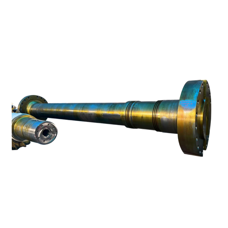
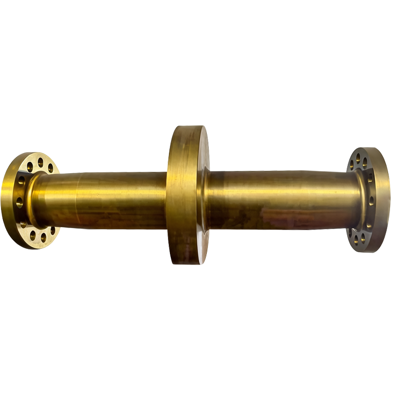
TOTEM's forged intermediate shaft is designed for marine propulsion shafting, where dimensional control, surface condition, runout, and nondestructive inspection are important parts of shaft quality management.
Evaluate Every Indication Before Assigning Fracture Risk
Finding an indication is not the end of marine propeller shaft fatigue crack inspection. The next task is deciding whether the indication is relevant, whether it represents an actual crack, and how its location affects fracture risk.
First, document the indication before altering the surface. Record its position relative to a keyway, shoulder, fillet, coupling, journal, or other identifiable datum. Note its orientation, approximate visible extent, inspection method, surface condition, and any associated fretting, corrosion, scoring, or deformation. Repeat the examination if the signal is inconsistent, and use another technically suitable method where confirmation or depth information is necessary.
A crack-like linear indication at a highly stressed transition should not be evaluated in the same way as an isolated non-relevant indication caused by geometry. Similarly, crack length alone is not enough to rank risk. Location, orientation relative to principal stresses, material, section diameter, remaining ligament, operating loads, evidence of growth, corrosion environment, alignment condition, and previous damage history can all influence the significance of the defect.
A practical risk framework can therefore use three levels without inventing universal dimensional limits. An indication shown to be non-relevant after repeat examination may return to normal inspection control. An unresolved linear indication should trigger engineering review and additional NDT rather than continued operation based on appearance alone. A confirmed crack in a critical load-carrying section should be treated as a potential fracture hazard until an approved engineering assessment determines the permitted action.
Trend information adds important context. If the same area develops repeated indications, fretting becomes more pronounced, runout changes, or operating vibration increases, the risk picture changes even when a single measurement remains within a historical limit. Growth and recurrence often reveal more about the active damage mechanism than one isolated inspection result.
This principle also applies to other heavily loaded rotating shafts. A 38CrNi3MoVA propulsion shaft relies on controlled forged material, machining accuracy, straightness, coaxiality, and surface quality in high-load transmission service. Inspection decisions must therefore consider both material integrity and geometry rather than treating NDT as an isolated quality check.
Make Removal and Repair Decisions Around the Cause, Not Only the Crack
A confirmed fatigue crack should not automatically lead to local grinding followed by immediate return to service. Removing visible crack material does not correct the mechanism that initiated it, and uncontrolled material removal may change a fillet radius, reduce shaft diameter, or introduce new machining marks.
The first decision is whether the affected shaft section can safely remain in service while further assessment is performed. For a confirmed crack in a critical torque- or bending-carrying region, removal from service pending technical evaluation is generally the prudent approach. Exact acceptance limits cannot be generalized because they depend on shaft design, material, dimensions, loading, inspection procedure, applicable classification requirements, and approved repair criteria.
Repair feasibility should then consider whether the complete crack can be removed, whether sufficient section remains, whether the original geometry and surface condition can be restored, and whether the repair process affects metallurgy or residual stress. Welding, machining, heat treatment, or dimensional restoration should never be selected simply because they can physically close or remove an indication. The repaired shaft still has to satisfy the engineering requirements governing its load-carrying function.
Prevention should address the initiation mechanism identified during inspection. Keyway fit, transition radii, surface finish, coupling condition, bearing support, alignment, lubrication, sealing, corrosion protection, and assembly practices can all influence marine shaft fatigue. Abnormal events such as propeller impact, grounding, severe entanglement, or sudden vibration changes can also justify targeted inspection before the normal interval.
Inspection history is especially valuable. Preserve NDT maps, dimensional measurements, photographs, runout data, and maintenance observations so that the next survey can distinguish a stable surface feature from a developing defect. Fatigue risk management becomes much stronger when each inspection is compared with a baseline rather than treated as an independent pass-or-fail event.
Conclusion
Reliable marine propeller shaft fatigue crack inspection combines location-based inspection, careful surface and dimensional checks, appropriate NDT, indication verification, and engineering assessment. The critical question is not simply whether an indication exists, but whether its location, depth, growth behavior, and operating conditions create a credible fracture path.
Shanghai TOTEM Machinery Co., Ltd. is a manufacturer of precision mechanical components with shaft machining and production capabilities. Effective dimensional control, surface management, and material-integrity inspection help support the requirements that matter throughout a propulsion shaft's service life.
FAQ
Q: How often should marine propeller shaft fatigue crack inspection be performed?
A: Inspection intervals depend on shaft design, service history, classification requirements, operating conditions, previous indications, and abnormal events. Higher-risk findings can justify inspection before the normal scheduled interval.
Q: Is magnetic particle inspection suitable for every marine shaft?
A: No. MPI requires ferromagnetic material. For suitable shafts it detects surface and near-surface discontinuities, while PT or UT may be required for other materials or defect locations.
Q: Can visual inspection confirm that a propeller shaft has no fatigue cracks?
A: No. Visual inspection identifies surface damage and suspicious areas, but fine or subsurface cracking may require MPI, PT, UT, or another approved nondestructive examination technique.
Q: Should a suspicious shaft indication be ground away before NDT?
A: Not before it is documented and evaluated. Premature grinding can remove evidence, alter local geometry, reduce section thickness, and make the original damage mechanism harder to determine.
Q: Which locations deserve priority during propeller shaft crack detection?
A: Priority areas commonly include keyways, fillets, shoulders, diameter transitions, coupling interfaces, journal edges, threaded regions, damaged surfaces, corrosion pits, and locations showing fretting or previous repairs.
Q: Does finding a crack always mean the shaft must be replaced?
A: Not automatically. The decision depends on crack location, extent, material, shaft geometry, loading, repair feasibility, and applicable acceptance requirements, but confirmed critical cracks require formal engineering assessment.
