
Views: 0 Author: Site Editor Publish Time: 2026-08-17 Origin: Site
The crosshead functions as a vital mechanical junction in rotating equipment. It translates rotational force from the crankshaft into the pure linear motion required for compression. When reciprocating compressor crosshead wear exceeds designated tolerances, it initiates a severe chain reaction. This degradation triggers a cascade of mechanical failures across the entire drive train and disrupts critical cylinder alignment. Unplanned downtime quickly follows. Facilities face secondary damage to related components and experience sharply elevated maintenance costs. We designed this guide to help you manage these challenges effectively. We provide rotating equipment engineers and maintenance managers with an evidence-based framework for field execution. You will learn how to diagnose wear accurately and execute precise clearance inspections. We also offer clear parameters for making repair versus replacement decisions to restore reliability.
Root Cause Identification: Most crosshead wear stems from lubrication breakdown, severe misalignment, or improper connecting rod clearances, rather than inherent material defects.
Precision Inspection: Verifying top and bottom crosshead-to-guide clearances using proper instrumentation (feeler gauges, dial indicators) is non-negotiable for baseline condition assessment.
Systematic Impact: Excessive wear doesn't isolate itself; it directly impacts compressor piston rod runout and accelerates packing failure.
Sourcing Strategy: Selecting replacement gas reciprocating compressor parts requires evaluating suppliers on material integrity (e.g., babbitt quality), dimensional accuracy, and documented compliance with OEM or API standards.
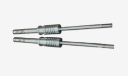
The crosshead serves a highly specialized function within a compressor frame. It absorbs the extreme lateral forces generated by the rotating crankshaft. By absorbing these side loads, it maintains the true linear trajectory of the Compressor Piston Rod. Without a properly functioning crosshead, rotational forces would push the rod directly into the cylinder walls, destroying the machine in minutes. A healthy crosshead assembly glides smoothly on a hydrodynamic oil film, keeping metal-to-metal contact at zero.
When clearances widen beyond acceptable limits, a destructive domino effect begins. You will first notice audible changes and increased vibration. Here is how the damage spreads through the system:
Knocking and Vibration: Excessive clearance allows the crosshead to slam against the upper and lower guides during load reversals. This impact creates a distinct knocking sound and sends shockwaves through the frame.
Stress Transfer: The kinetic energy from these impacts does not dissipate harmlessly. It transfers directly to the Compressor Connecting Rod and the crosshead pin bearing, risking premature fatigue failure.
Accelerated Component Wear: As the crosshead slops vertically, the attached rod also moves off-center. This deflection aggressively wipes out piston rod packing rings, scores cylinder liners, and compromises rider bands.
Mechanical degradation translates directly into severe operational risks. A worn crosshead prevents the piston from achieving optimal stroke geometry, significantly reducing overall volumetric efficiency. If left unchecked, the continual pounding risks catastrophic power-end failure. A shattered crosshead or broken connecting rod will penetrate the compressor frame, leading to hazardous gas releases and prolonged turnaround times.
Understanding why crossheads fail allows you to implement better preventative measures. Failures rarely occur due to poor manufacturing. They almost always result from adverse operating conditions.
The crosshead relies entirely on pressurized lubrication. Inadequate oil flow instantly compromises the hydrodynamic film separating the shoe from the guide. When oil viscosity drops too low, or if the system lacks sufficient pressure, the babbitt overlay makes direct contact with the cast iron guide. This results in immediate babbitt wiping and deep scoring. Particulate contamination also poses a severe threat. Dirt, metal shavings, or degraded oil sludge act like sandpaper trapped between moving surfaces.
Oil temperature fluctuations further complicate lubrication. High temperatures thin the oil, reducing film thickness. Cold starts pump thick, unyielding oil that cannot penetrate the tight clearances in the crosshead guide, leading to dry friction during the critical first minutes of operation.
Precision alignment dictates compressor health. Cylinder-to-frame misalignment forces the crosshead to run "hard" on one side of the guide. This localized pressure breaks the oil film and causes uneven wear patterns. You will typically see severe wiping on one corner of the crosshead shoe while the opposite side looks pristine.
External factors also drive misalignment. Foundation settling over time can physically twist the compressor frame. Similarly, uneven thermal growth between the hot cylinder and the cooler crankcase can distort the crosshead guide, pinching the Crosshead Block Assembly during operation.
Compressors are designed for specific gas compositions and pressures. Liquid ingestion (slugging) introduces incompressible fluids into the cylinder. This creates massive pressure spikes that push the crosshead shoes violently against the guides. Consistently operating above rated gas rod loads heavily stresses the entire assembly.
Internal component degradation also alters load distribution. Worn crosshead pins or failing connecting rod bushings allow the crosshead to tilt slightly during the stroke. This tilt concentrates thousands of pounds of force onto a tiny surface area, rapidly destroying the babbitt material.

Accurate inspection separates reliable operations from recurring failures. You must establish rigorous measurement protocols during every overhaul.
Begin with a thorough visual examination. Clean the crosshead shoes and inspect the babbitt surfaces. Look for flaking, embedded debris, or wide smooth patches that indicate wiping. Pay special attention to the edges, as edge-loading indicates severe misalignment.
Visual checks alone are insufficient for the main structure. You must perform Magnetic Particle Inspection (MPI) or dye penetrant testing on the main block casting. These tests reveal microscopic stress fractures around the pin bore and the threaded rod connection. Finding a crack here means the component is condemned.
Clearance measurement requires specific tools and a steady hand. You will need long feeler gauges (at least 12 inches), precision micrometers, and dial indicators.
Follow this procedure to measure clearances accurately:
Position the Crosshead: Bar the compressor over until the crosshead sits at inner dead center (IDC).
Measure Top Clearances: Insert a long feeler gauge between the top crosshead shoe and the upper guide. Slide it in at all four corners (front, back, left, right). Record the measurements.
Measure Bottom Clearances: Repeat the feeler gauge process for the bottom shoe. (Note: The bottom clearance is often zero if the assembly rests on the bottom guide, but you must verify this).
Reposition and Repeat: Bar the compressor to outer dead center (ODC) and repeat the measurements to check for guide taper or distortion.
Check Side Clearances: Use a standard feeler gauge to measure the gap between the side of the crosshead and the guide rails to ensure lateral tolerance.
Evaluating these tolerances requires the OEM manual. Compare your measured data against baseline specifications. A common best practice dictates that if clearances exceed the OEM maximum by 50%, you must intervene.
Rod runout serves as an excellent secondary indicator of crosshead health. Place a dial indicator on the rod near the packing case. Bar the compressor through a full revolution. Monitor both horizontal and vertical deflection. High vertical runout usually indicates bottom crosshead shoe wear. High horizontal runout points to crosshead guide misalignment or a severely cocked crosshead block.
Crosshead Clearance and Runout Evaluation Chart
| Measurement Type | Symptom Observed | Probable Root Cause | Required Action |
|---|---|---|---|
| Vertical Rod Runout | Exceeds 0.002 inches per inch of stroke | Bottom crosshead shoe wear or guide drop | Inspect babbitt thickness; shim or replace shoes. |
| Horizontal Rod Runout | Exceeds 0.0015 inches per inch of stroke | Frame-to-cylinder misalignment | Perform laser alignment on cylinder and crosshead guide. |
| Top Guide Clearance | Gap exceeds OEM maximum by >0.005" | Babbitt wiping or incorrect shoe installation | Remove shoe, measure thickness, verify pin bore integrity. |
| Side Guide Clearance | Tight on one side, excessive on the other | Thermal distortion or foundation twist | Check frame web deflection; inspect foundation bolts. |
When you discover unacceptable wear, you face a critical decision. Do you repair the existing component or purchase a new one? Making the wrong choice leads to wasted budget or repeated failures.
Repairing a crosshead shoe is a highly viable option under specific conditions. If you catch the wear early, you might only find minor babbitt scoring. As long as the underlying cast iron or steel structural shoe remains completely undamaged, repair makes sense.
When your downtime schedule allows, you can send the worn shoes to a specialized machine shop. They will melt out the old material and re-pour new babbitt using centrifugal casting techniques. After pouring, they machine the shoe back to standard dimensions. If your crosshead guides are deeply worn, the shop can machine the guides and pour oversized babbitt on the shoes to restore factory clearances.
Some damage crosses the point of no return. You must replace the assembly if you find deep scoring that gouges the steel backing. Structural cracks discovered during MPI testing require immediate replacement. You cannot safely weld a cracked crosshead block.
Severe pin bore elongation also mandates replacement. If the bore that holds the crosshead pin becomes oval-shaped due to pounding, it will never hold the pin securely again. Finally, compare lead times. If the cost and wait time for a specialized repair exceed the procurement of a new, ready-to-ship component, replacement wins.
Choosing the right vendor for Gas Reciprocating Compressor Parts requires strict diligence. Evaluate suppliers based on material standards first. They must provide verification of their babbitt composition (typically high-tin ASTM B23 Grade 2) and block metallurgy.
Demand dimensional certification. The supplier must prove strict adherence to OEM geometric tolerances. Finally, assess their availability and support. Look for vendors who offer rapid lead times, in-house engineering support, and robust warranty terms for their replacement assemblies.
Fixing a broken crosshead solves the immediate problem. Upgrading your maintenance strategy prevents it from happening again.
Modern sensors eliminate guesswork. Utilize frame vibration sensors to monitor changes in mechanical frequencies. Acoustic monitoring can detect early-stage knocking weeks before it becomes audible to the human ear. Routine oil analysis is equally critical. Track bearing wear metals like tin, lead, copper, and iron. A sudden spike in tin or lead levels gives you advance warning that the crosshead babbitt is failing.
How you assemble the machine dictates how long it will run. Adopt laser alignment techniques during overhauls to ensure the cylinder, guide, and frame sit perfectly true. Abandon outdated wire-line methods. Ensure your mechanics use proper torque specifications and hydraulic tensioning on connecting rod bolts and crosshead nuts. Over-tightening distorts the assembly and pinches the running clearances.
Data drives reliability. Document your clearance readings at every single turnaround. Build a historical database of top, bottom, and side clearances. This data establishes accurate wear trends. Once you understand the specific wear rate of your compressor, you can predict future replacement intervals and order parts well in advance.
Managing reciprocating compressor crosshead wear is essential for maintaining total equipment reliability. The crosshead bridges the power end to the compression end; any failure here compromises the entire machine. Diligent inspection using precise tools, combined with rigorous root cause analysis, prevents repetitive and dangerous failures. Monitor your lubrication closely, enforce strict alignment tolerances, and never ignore excessive rod runout.
Actionable next steps for your facility:
Implement a mandatory clearance measurement protocol using long feeler gauges during your next scheduled outage.
Establish an oil sampling program focused on tracking tin and lead particulate trends.
Audit your current inventory of replacement shoes and blocks to ensure they meet stringent API/OEM material specifications.
Consult with specialized rotating equipment engineers if your compressor exhibits chronic, unexplainable rod runout.
A: It varies by frame size, OEM, and operating temperature, but generally ranges from 0.005 to 0.015 inches (or specific OEM metric equivalents). Always defer to the specific compressor manual for baseline and condemning limits.
A: Excessive crosshead clearance allows vertical or lateral movement, causing the piston rod to deflect. This runout prematurely wears the rod packing, leads to gas leaks, and can score the cylinder.
A: Yes, if the underlying structural material of the crosshead block assembly is uncompromised, the shoe can often be re-babbitted, machined, and refitted to proper tolerances by a qualified shop.
A: Pin failure is typically caused by insufficient lubrication, excessive clearance in the compressor connecting rod bushing, or extreme reversing loads that prevent proper oil film formation.


