
Views: 0 Author: Site Editor Publish Time: 2026-08-19 Origin: Site
Reciprocating compressors rely on precise mechanical synchronization. They operate under extreme industrial conditions where every moving part must perform flawlessly. However, continuous operation without proper load reversal leads to rapid failure. These component failures are often catastrophic and highly unpredictable. To prevent costly disasters, you must fully understand the core mechanism at play.
The transition between tension and compression forces along the piston rod is strictly mandatory. This alternating force creates a mechanical toggling action. It maintains the hydrodynamic lubrication film within the internal bushings. Operators and reliability engineers face a significant challenge in monitoring this dynamic. They must evaluate real-time condition monitoring systems effectively. Ensuring API 618 compliance and exploring strategic component upgrades are equally critical tasks. Taking these proactive steps protects expensive capital equipment. Furthermore, addressing reciprocating compressor rod load reversal prevents catastrophic unplanned downtime across your facility.
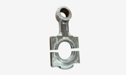
Consistent reciprocating compressor rod load reversal is strictly required to allow oil to flow into the crosshead pin bushing; without it, lubrication films collapse.
Sustained non-reversal destroys the crosshead pin, bushing, and eventually impacts the compressor connecting rod and crankshaft.
API 618 and OEM guidelines dictate specific minimums for reversal duration (degrees of crank angle) and force magnitude.
Evaluating and implementing dynamic cylinder pressure monitoring is the most reliable method for detecting real-time rod load anomalies.
Hydrodynamic lubrication forms the lifeblood of heavily loaded industrial machinery. The Crosshead Assembly specifically requires these alternating forces to function correctly. During the suction stroke, internal cylinder pressures pull the rod, creating tension. During the discharge stroke, pushing forces create heavy compression. This constant toggling action literally lifts the crosshead pin away from its bushing wall for a fraction of a second. When the pin lifts, fresh lubricating oil sweeps into the microscopic clearance space. This sweeping action replenishes the protective fluid film.
You must understand the physics of non-reversal to grasp why compressors fail. Reciprocating masses naturally generate inertia. Differential gas pressures push against these inertia forces. Sometimes, gas pressures fail to overcome reciprocating inertia. If the internal gas force remains excessively high or low, the net force never crosses the zero mark. The rod stays trapped in constant compression or constant tension. Because the pin never lifts off the bushing, fresh oil cannot enter the clearance gap. The existing oil film quickly squeezes out entirely.
The system-wide impact of this failure is severe. Energy does not just disappear. Unrelieved mechanical stress transfers directly from the Compressor Piston Rod back into the crosshead. From there, the binding forces travel into the Compressor Connecting Rod. Every connected component feels the destructive strain.
Engineers often calculate theoretical load behaviors during the initial design phase. They assume ideal valve behavior and perfect gas compositions. We must issue a strong assumption warning here. Real-world conditions rarely match theoretical models. Compressor valves leak. Process conditions shift unexpectedly. Gas compositions fluctuate over time. These daily field variables drastically alter reversal characteristics. You cannot rely solely on the original design-day calculations to guarantee safe operation.
Crosshead assembly failures represent one of the most common and destructive scenarios. The primary failure mode begins with oil starvation. Without the vital oil film, dry metal grinds against dry metal. Extreme heat generates almost instantly. The soft babbitt material inside the bushing begins wiping away under the immense friction. Melted babbitt smears across oil supply holes, permanently blocking future lubrication. Ultimately, the pin seizes completely within the bore.
When the pin seizes, it creates massive stress on the connecting rod. The pin can no longer articulate smoothly as the crankshaft rotates. Erratic load distributions force the rod to bend slightly with every single stroke. The connecting rod is designed for massive axial column strength, not lateral bending forces. These unnatural bending stresses lead to rapid structural deterioration. Micro-cracks form along the beam structure, setting the stage for a sudden snap.
Severe load anomalies do not stop there. They propagate down the entire drivetrain. The resulting vibration and misalignment heavily impact the main bearings. Eventually, the Compressor Crankshaft faces high risks of fatigue failure. Imbalanced forces twist the throws and score the journals. Replacing a damaged crankshaft requires a complete frame teardown.
Quantifying the cost of inaction reveals a stark reality. Ignoring these operational risks invites disaster. Unplanned downtime costs thousands of dollars per hour in lost production. Complete frame rebuilds consume massive maintenance budgets and require weeks of labor. In contrast, investing in early detection and intervention costs a fraction of a catastrophic failure. Proactive monitoring preserves your capital assets.

The industry relies heavily on established evaluation criteria to guarantee machine safety. The API 618 standard dictates strict guidelines for reciprocating compressors. It typically requires a minimum of 15 degrees of crank angle reversal. It also mandates a 3% minimum force magnitude. The 15-degree duration provides just enough milliseconds for oil to sweep into the bushing. The 3% magnitude ensures the force pushes the pin far enough across the clearance gap.
Original Equipment Manufacturers establish their own minimum allowable limits. Manufacturers such as Ariel or Dresser-Rand engineer proprietary pin reversal limits for their specific frame sizes. You must strictly adhere to these OEM specifications during daily operation. They often provide detailed performance charts outlining acceptable operating envelopes. Ignoring OEM guidelines automatically voids warranties and guarantees premature wear.
Evaluating existing assets requires a structured approach. Process conditions change heavily over the years. Gas streams become heavier or lighter. Suction pressures drop as field wells deplete. You need a solid framework to audit current compressor performance against the original engineering standards.
Evaluation Criteria for Reciprocating Compressor Performance
| Evaluation Category | Standard Limit | Primary Focus Area | Risk if Ignored |
|---|---|---|---|
| API 618 Minimum Duration | 15 degrees of crank angle | Time allowed for oil replenishment | Babbitt wiping and rapid overheating |
| API 618 Minimum Magnitude | 3% peak load force | Distance the pin travels in the bore | Incomplete oil film distribution |
| OEM Proprietary Limits | Varies by frame/model | Specific structural tolerances | Warranty void and fatigue fracture |
| Process Condition Audit | Field specific baselines | Gas weight and pressure drift | Chronic, undetected load anomalies |
Operators must choose between periodic calculations and direct measurement. Periodic analytical software calculations offer a helpful snapshot. Reliability engineers input current gas data to estimate theoretical loads. However, they remain limited by their static nature. Continuous online monitoring tells the real, unvarnished story. Direct measurement catches transient anomalies. It reveals exactly what happens during startup, shutdown, and process upsets.
Dynamic cylinder pressure monitoring serves as the most robust solution available. Installing high-speed pressure transducers directly on the cylinders unlocks real-time visibility. The monitoring system captures pressure data at every fraction of a degree of rotation. Software calculates real-time indicated rod loads instantly. It tracks the precise degrees of reciprocating compressor rod load reversal continuously. This method leaves zero room for guesswork.
We also utilize secondary indicators like crosshead vibration and temperature sensors. These sensors play a supporting role in condition monitoring. However, you must recognize their primary limitation. Temperature spikes are lagging indicators. By the time a crosshead temperature sensor triggers an alarm, the babbitt material is already melting. Mechanical failure is already occurring. Vibration sensors indicate loose or heavily damaged components. Neither prevents the initial oil starvation.
Implementing advanced continuous monitoring systems involves certain risks. Retrofitting older compressors brings immediate complexity. You face substantial challenges when wiring hazardous areas.
Routing intrinsically safe sensor wiring across older compressor frames.
Synchronizing high-speed transducer data accurately with the crankshaft encoder.
Integrating complex data outputs into legacy SCADA or DCS networks.
Tuning alarm thresholds carefully to prevent widespread operator alert fatigue.
Alert fatigue is highly dangerous. If alarms trigger too frequently due to poor tuning, operators simply acknowledge and ignore them. Precise calibration is mandatory for a successful monitoring retrofit.
When you detect poor reversal, you must act quickly. Process adjustments offer the fastest mitigation strategy. Sometimes, altering suction or discharge pressures shifts the load curve back into a safe zone. Modifying cylinder clearances also helps rebalance the internal forces. Utilizing existing clearance pockets can restore acceptable load reversal limits without requiring a full machine shutdown. Process engineers should run simulations before adjusting setpoints in the field.
If process changes cannot solve the underlying problem, evaluate component upgrades. Upgrading mechanical parts often delivers a strong return on investment. Installing heavier crossheads alters the inertia balance of the entire throw. Upgrading to specialized pin designs provides another layer of defense. These custom pins feature engineered lubrication grooves. They safely operate under marginal reversal conditions by aggressively forcing oil into the load zone.
Shortlisting the right solution requires careful evaluation. You must weigh the urgency of the problem against your available budget and downtime windows.
Conduct a comprehensive process engineering audit to verify current gas compositions and pressures.
Evaluate the feasibility of a monitoring hardware retrofit for continuous data visibility.
Schedule an immediate component overhaul if vibration data or temperature trends indicate severe wear.
Do not wait for a catastrophic breakdown to force your hand. The most actionable next step is initiating a comprehensive rod load analysis today. Consult with a reliability specialist. Review your current operational data. Compare your actual running pressures against the original OEM curves.
Reciprocating compressor rod load reversal is far more than an abstract engineering concept. It represents a strict mechanical requirement for machine survival. Proper force reversal keeps lubricating oil flowing and critical metal components safely separated. Sustained non-reversal destroys crosshead assemblies and forces massive bending stresses down the drivetrain.
Investing in precise dynamic pressure monitoring pays massive dividends over the lifecycle of your equipment. Adhering closely to API 618 standards and OEM limits protects your entire drive train. Taking these proactive steps ensures long-term asset profitability. When you prioritize load reversal management, your compressors run safely, efficiently, and continuously for years to come.
A: The industry standard, governed by API 618 guidelines, typically requires a minimum of 15 degrees of crank angle reversal. It also mandates a peak load magnitude of at least 3%. However, specific OEM manuals provide proprietary limits based on frame size. You must evaluate both standards.
A: Common causes include significant suction or discharge pressure changes and unexpected gas composition variations. Running a cylinder completely unloaded also eliminates differential gas pressure. Additionally, faulty or leaking compressor valves heavily disrupt the internal pressures needed to overcome reciprocating inertia.
A: No. Crosshead temperature is strictly a lagging indicator. By the time a temperature spike registers on the sensor, the babbitt material is already melting and failing. You must use dynamic cylinder pressure monitoring to calculate real-time load forces for predictive intervention.
A: Non-reversal forces the rod into a state of continuous compressive or tensile stress. Without the brief mechanical relief of toggling, the rod cannot shed its load. This constant stress leads to accelerated wear, bending forces, and a high probability of sudden fatigue fracture.


