
Views: 0 Author: Site Editor Publish Time: 2026-08-16 Origin: Site
Rotor imbalance acts as a primary driver of catastrophic failure in power generation and industrial drive systems. Unchecked vibration rapidly accelerates bearing wear and inevitably triggers unplanned downtime. Decision-makers often face a critical dilemma after major maintenance events. Should you mandate field balancing, low-speed shop balancing, or high-speed balancing at operational speeds? Making the wrong choice threatens operational safety. It also guarantees severe mechanical degradation over time.
We provide a vendor-agnostic framework to help you navigate this complex process. You will learn exactly when steam turbine rotor dynamic balancing becomes strictly mandatory. We also explain how to verify the technical integrity of the execution. By understanding objective data requirements and rigid industry standards, you can secure long-term equipment reliability. You will learn to evaluate facility capabilities, demand transparent reporting, and eliminate guesswork from your next major outage.
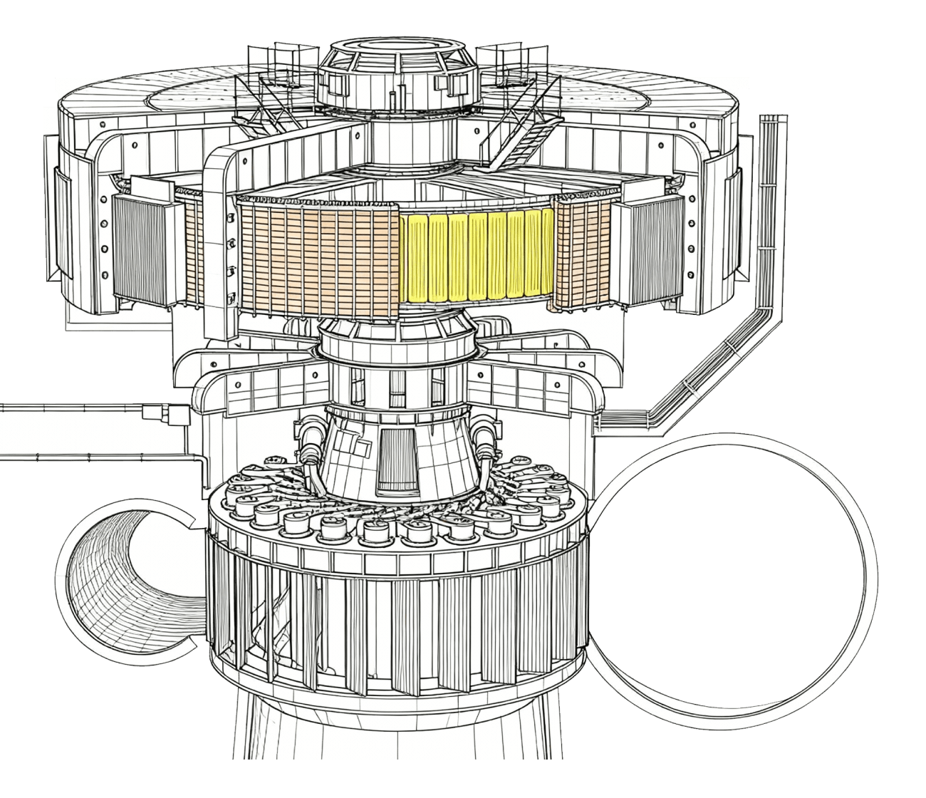
Dynamic balancing is not just preventative; it is mandatory following specific maintenance triggers like reblading, shaft machining, or severe thermal bowing.
The choice between low-speed (rigid) and high-speed (flexible) balancing depends on operating RPM, rotor flexibility, and critical speed thresholds.
Proper verification requires objective data: strict adherence to ISO 21940 / API 612 standards, transparent residual unbalance reporting, and vibration phase analysis.
Imbalance verification must include inspecting interacting components, as prolonged vibration severely degrades associated Steam Turbine Parts, particularly bearings and seals.
Operators cannot rely on guesswork to determine balancing needs. You must treat dynamic balancing as a mandatory requirement following specific operational events. Ignoring these triggers invites severe mechanical failure. We classify these mandatory triggers into four primary categories. Each category represents a significant alteration to the mass distribution or physical geometry of the machine.
Post-Repair and Modification: Any physical alteration requires immediate balancing. This rule applies strongly after installing a Customized Rotor Shaft. It also applies to reblading procedures, welding repairs, or machining tasks. Removing or adding significant material shifts the center of gravity. Even minor geometric deviations multiply into massive centrifugal forces at high speeds. You cannot skip this step after significant shop interventions.
Vibration Alarm Thresholds: Sustained increases in radial vibration demand investigation. You must monitor vibration levels against baseline OEM parameters. Approaching 3 to 4 mils peak-to-peak typically acts as a hard limit. This threshold depends heavily on machine size and operating speed. Once vibration triggers these alarms continuously, internal mass unbalance is a highly probable cause. Immediate correction prevents sudden component shearing.
Thermal Bowing and Rubbing: Rotors frequently suffer permanent set or bowing during abnormal operations. Water induction introduces rapid, uneven cooling across the metal surface. This phenomenon creates severe thermal distortion. Radial rubbing during operation also generates localized hot spots. These hot spots permanently warp the metal. Correcting this bow requires specialized straightening procedures followed by rigorous balancing.
Scheduled Overhauls: Standard maintenance protocols integrate balancing into major outage scopes. Outages provide the perfect window to baseline the Steam Turbine Rotor Shaft before reassembly. Proactive baseline checks detect hidden mass shifts. They ensure the unit returns to service smoothly. You avoid discovering vibration issues only during the final startup sequence.
Common mistakes occur when teams assume minor repairs do not affect mass distribution. Small welds or single blade replacements can drastically alter dynamic behavior. Always default to a mandatory balance check following any physical intervention.

Selecting the correct balancing method dictates the success of the operation. You must match the balancing technique to the specific flexibility and operating speed of the equipment. We break these solutions into two distinct categories. Understanding their differences prevents critical operational failures.
Low-speed balancing typically addresses rigid body dynamics. Operators execute this process on hard-bearing machines. The machine rotates the assembly at a relatively low RPM. This speed stays well below the first critical speed of the unit.
This approach focuses strictly on mass center correction. It does not account for modal deflection. The process assumes the metal structure remains perfectly stiff. Low-speed methods work perfectly for smaller, rigid units. We also use this method as an initial correction step. You must pre-balance heavily modified units at low speeds before moving them to high-speed facilities.
High-speed balancing becomes essential for modern, high-capacity steam turbines. These machines operate above their first critical speed. As they pass through these critical thresholds, the shaft physically bends. This bending is known as modal deflection.
You cannot correct modal deflection on a low-speed machine. Facilities conduct high-speed balancing inside a vacuum spin pit. The vacuum eliminates windage friction. This prevents the blades from overheating at operational speeds. Technicians perform complex modal shape analysis. They correct unbalance at the exact deflections experienced during normal operation. Skipping this high-speed step on a flexible unit guarantees disaster. It guarantees high vibration at operating load. This oversight leads to immediate outage scenarios upon startup.
Table 1: Technical Comparison of Balancing Approaches
| Feature | Low-Speed (Rigid) Balancing | High-Speed (Flexible) Balancing |
|---|---|---|
| Operating RPM | Well below first critical speed (Typically 100-500 RPM) | At or above continuous operating speed (e.g., 3600 RPM+) |
| Facility Requirement | Standard hard-bearing balancing machine | Vacuum spin pit / bunker facility |
| Correction Focus | Static mass center correction | Modal shape and deflection analysis |
| Primary Use Case | Rigid units or initial pre-balancing | Large units operating above critical speeds |
| Risk of Skipping | Low for rigid units; catastrophic for flexible units | Guaranteed high vibration under operational load |
Balancing the central rotating mass solves only part of the problem. Prolonged imbalance acts like a hammer on internal machinery. It transfers destructive kinetic energy directly to adjacent assemblies. You must conduct a systemic audit of these interacting components. Failing to address collateral wear results in suboptimal mechanical runs even after perfect balancing.
Severe imbalance forces the shaft to hammer against its supports. This kinetic energy transfers directly to the journals. It degrades the structural integrity of the bearing material. You must rigorously inspect these supports. Outline the necessity of inspecting or replacing the DIN Sliding Bearing elements. Tilt-pad bearings also require meticulous examination. Look for wiping, scoring, or babbitt fatigue. If the unit operated out of balance for extended periods, bearing replacement is usually mandatory.
Unbalance causes orbit eccentricity. The shaft moves in an enlarged, erratic circular path. This enlarged orbit forces the metal to grind against internal seals. Detail the need to verify labyrinth seal clearances carefully. Measure the gaps to ensure they remain within OEM specifications. Excessive rubbing wears down the seal teeth. This wear creates massive efficiency losses due to steam blow-by. You must also check internal seals for signs of babbitt material fatigue. Degraded seals compromise internal pressure boundaries.
We emphasize a systemic approach to post-imbalance recovery. Balancing the rotor in isolation is a common mistake. You must address wear on all adjacent Steam Turbine Parts simultaneously. Reassembling a perfectly balanced shaft into worn bearings creates new vibration modes. The enlarged clearances allow the shaft to float erratically. Conduct full non-destructive testing (NDT) on journals. Measure all clearances meticulously. A complete systemic audit guarantees a smooth, reliable return to service.
Dynamic balancing requires strict objective data. You cannot accept subjective assurances from service providers. You must demand empirical proof of success. We define success through rigid adherence to global standards and transparent data reporting.
You must mandate verification against established global frameworks. For special-purpose machinery, demand compliance with API 612. This standard dictates strict operational limits for advanced steam units. Furthermore, enforce the ISO 21940 series. Use ISO 21940-11 for rigid applications. Use ISO 21940-12 for flexible applications. These standards remove ambiguity. They establish clear, mathematical boundaries for acceptable vibration and residual mass.
Uper Calculation: Demand the exact calculation of the maximum allowable residual unbalance. Engineers refer to this value as Uper. It defines the absolute maximum heavy spot allowed on the metal.
Threshold Verification: Verify that the final balancing report shows residual unbalance well below the Uper threshold. Industry best practices typically aim for the 4W/N formula or better. The final mass log must prove compliance mathematically. Do not accept a report lacking these specific calculations.
Bode and Nyquist Plots: Require comprehensive data plots from the high-speed run. Bode plots map vibration amplitude against RPM. Nyquist plots map the polar coordinates of phase and amplitude. You must use these plots to verify vibration amplitude and phase angle stability. They prove the equipment remains stable through all critical speeds.
Runout Verification: Ensure electrical and mechanical runout (TIR) meets stringent API specifications. Measure these values directly on the probe target areas. The total indicator reading typically must remain below 0.25 mil. High runout introduces false signals to the vibration monitoring system. False signals mask true mechanical problems during normal operation.
Choosing the right service provider dictates the safety and accuracy of the balancing process. Not all facilities possess the necessary infrastructure. You must evaluate potential vendors systematically. Focus on facility capability, equipment accuracy, and data transparency.
High-speed flexible balancing demands massive infrastructure. You must verify the provider operates a legitimate vacuum bunker or spin pit. Check the physical weight and length limits of their facility. The pit must safely accommodate your specific equipment dimensions. Furthermore, the drive system must possess enough power. It must safely rotate the heavy mass to 110% of its continuous operating speed. Taking the unit to overspeed tests the mechanical integrity of the blades and centrifugal locks.
Accurate balancing relies entirely on precise instrumentation. Request current, formal calibration certificates for all balancing machine instrumentation. You must also request calibration data for their vibration probes. These certificates must demonstrate clear traceability to recognized national standards. Expired or untraceable calibration renders the entire process useless. It produces false mass corrections that ruin the shaft dynamics.
Reject simple "pass/fail" reports immediately. Black-box reporting hides poor workmanship. The vendor must provide comprehensive pre-balance and post-balance logs. You need the as-received unbalance mass data to understand the initial severity. You need the final unbalance mass logs to verify correction. Demand full access to phase angles and transient vibration data. Transparent reporting allows your engineering team to baseline the unit accurately for future predictive maintenance.
We must reiterate that dynamic balancing remains an exact, mathematical science. It is never a subjective service. The approach you select directly dictates the lifecycle reliability of your rotating equipment. Mandatory operational triggers demand immediate attention. Understanding the divide between low-speed rigid corrections and high-speed flexible modal analysis prevents catastrophic operational failures. Proper execution protects your infrastructure from destructive kinetic energy.
Your next steps require proactive planning. We advise decision-makers to audit their upcoming outage scopes immediately. Identify any units requiring significant modification or showing elevated vibration trends. Demand transparent Inspection and Test Plans (ITPs) from your chosen service providers. Finally, secure compliant balancing slots in certified vacuum facilities well in advance. Proactive scheduling ensures your critical assets receive the exact technical care they require to operate safely and efficiently.
A: Static balancing corrects single-plane unbalance, where the heavy spot causes the unit to roll to the bottom when resting on frictionless bearings. Dynamic balancing corrects multi-plane and couple unbalance. It resolves forces that cause the shaft to wobble or twist when rotating at high speeds.
A: Field balancing serves only for minor trim balancing. It corrects slight mass shifts using portable instruments. Major unbalance, severe bow correction, or complex modal shape correction strictly requires a shop environment with specialized hard-bearing machines or vacuum spin pits.
A: The entire process typically requires 5 to 10 days. This timeline accounts for meticulous setup, pumping down the vacuum chamber, and conducting successive high-speed runs. The exact duration depends heavily on the initial unbalance severity and the required modal corrections.
A: Vibration occurring only at specific loads often points to issues beyond mass unbalance. Common culprits include severe thermal sensitivity, shifting generator alignment under load, or underlying foundation resonance. These systemic issues mimic unbalance but require different diagnostic and corrective strategies.


