
Views: 0 Author: Site Editor Publish Time: 2026-08-04 Origin: Site
Finding marine propulsion shaft vibration causes on a large vessel is rarely a matter of inspecting the propeller alone. The same symptom can originate in propeller loading, shaft runout, alignment, bearing condition, coupling geometry, lubrication, or a resonant response of the shaft line and supporting structure.
Diagnosis becomes faster when vibration is classified by speed, load, temperature, and location before components are dismantled. This approach helps separate a repeatable excitation source from a condition that appears only when the drivetrain is hot, heavily loaded, or structurally deflected.
A vibration complaint becomes useful diagnostic information only after its operating pattern is defined. “The shaft vibrates” is too broad because different faults can produce similar motion at a single operating point. Start by recording where vibration is strongest, the shaft speed at which it begins, whether amplitude changes with propulsion load, and whether bearing temperature changes at the same time.
Speed behavior is the first separator. Vibration that grows steadily with rotational speed deserves investigation for rotating geometry problems such as imbalance, eccentricity, shaft runout, or coupling errors. A sharp peak confined to a narrow speed range can instead indicate resonance or a shaft-line dynamic response. Operating above or below the troublesome band may reduce the symptom temporarily, but this does not establish the root cause.
Load behavior adds another layer. If vibration remains moderate at the same RPM under light propulsion demand but increases substantially at higher thrust, examine propeller hydrodynamic loading, bearing reaction, coupling movement, and alignment changes under torque. If vibration is accompanied by increasing bearing temperature, lubrication condition and bearing loading move higher on the inspection priority.
Finally, record location. A high reading near one bearing does not automatically prove that bearing generated the vibration. The bearing pedestal, foundation, hull structure, or connected machinery may transmit or amplify vibration from another part of the shaft line. Compare several measurement positions before replacing the nearest component.
Operating patterns can reduce a long fault list to a manageable set before intrusive inspection begins. For large-vessel shaft lines, the relationship between shaft RPM and propulsion load is especially useful because identical rotational speeds may occur under significantly different hydrodynamic and structural conditions.
A vibration that is strongly RPM-dependent but comparatively insensitive to load should direct attention toward rotating geometry, balance, shaft straightness, flange condition, and speed-related resonance. If a repeatable peak occurs only within one narrow RPM band and then declines, do not assume the shaft is simply bent. The shaft line, bearings, supporting structure, and attached equipment can form a dynamic system with speed-sensitive response.
A vibration that becomes much stronger as load increases at similar RPM points toward a different group of possibilities. Propeller inflow, blade condition, hydrodynamic excitation, bearing loading, shaft bending, or alignment changes under operating forces may be involved. Static alignment alone does not always represent the shaft line under actual operating conditions because hull deflection, propeller forces, bearing behavior, and temperature can alter the system.
Temperature helps distinguish problems that develop with time under load. If vibration is followed by a gradual increase in bearing temperature, inspect oil supply, lubricant condition, clearances, journal contact, bearing reaction, and shaft alignment rather than treating the vibration as an isolated balance problem. Conversely, a vibration that appears immediately at a repeatable RPM without abnormal temperature may justify earlier investigation of excitation and resonance.
The diagnostic value comes from combining variables. RPM, vessel speed, propulsion load, bearing temperature, vibration location, operating duration, draft, and recent maintenance history should be logged together. One parameter rarely identifies the fault reliably on its own.
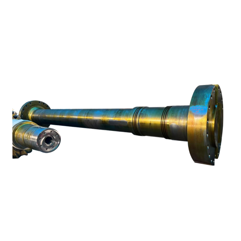
Propeller-related excitation is a logical starting point when vibration changes after impact, repair, fouling, or a noticeable change in hydrodynamic behavior. Blade damage, unequal blade geometry, deposits, cavitation-related excitation, or non-uniform inflow can impose periodic forces on the shaft. These forces then travel through the propulsion shafting, making a downstream symptom easy to mistake for a bearing or coupling fault.
The shaft itself must be evaluated as both a rotating component and part of an aligned elastic system. Excessive runout, local bending, eccentric journals, damaged flange interfaces, or dimensional errors can produce cyclic displacement and load variation. Critical shaft geometry therefore cannot be judged by material strength alone. Straightness, coaxiality, journal condition, flange accuracy, surface condition, and the relationship between adjacent shaft sections all matter.
Shanghai TOTEM Machinery Co., Ltd.’s forged propulsion shaft includes dimensional and geometric control relevant to propulsion shaft applications, including straightness, coaxiality, runout, surface condition, and inspection requirements. These factors are particularly important where rotating geometry can contribute to repeated shaft excitation.
Intermediate sections deserve equal attention because a long shaft line can distribute a geometric or alignment error over several supports. A marine intermediate shaft interfaces with adjacent shaft sections, couplings, and bearings, so journal geometry, flange faces, coaxiality, runout, and alignment condition should be considered as one connected system rather than independent inspection items.
Bearings introduce another failure path. Incorrect bearing reaction, unsuitable clearance, lubrication problems, journal wear, pedestal displacement, or alignment errors can alter the oil-film condition and increase local load. Persistent temperature rise together with vibration is therefore more significant than either symptom alone. Replacing a damaged bearing without identifying why its load or lubrication condition became abnormal risks repeating the failure.
A useful diagnosis moves from operating evidence to non-invasive checks and only then to dismantling. Changing several components simultaneously destroys valuable evidence and makes it difficult to verify which action corrected the original shaft line vibration.
| Observed Pattern | Higher-Priority Checks | Possible Mechanisms |
|---|---|---|
| Vibration rises broadly with RPM | Propeller balance, shaft runout, flange geometry, coupling condition | Imbalance, eccentricity, bent or inaccurate rotating geometry |
| Strong peak in a narrow RPM band | Vibration spectrum, supports, foundations, shaft dynamic behavior | Resonance, whirling, structural amplification |
| Higher vibration at similar RPM but greater load | Propeller condition, bearing reaction, alignment, coupling movement | Hydrodynamic excitation, load-dependent bending or alignment |
| Vibration plus increasing bearing temperature | Lubrication, bearing clearance, journal contact, bearing load | Oil-film deterioration, overload, misalignment |
| Local vibration after shaft-line maintenance | Coupling faces, journal runout, bearing position, assembly records | Installation error, incorrect offset, geometric mismatch |
For a systematic inspection, begin with operating data rather than component replacement. Record vibration at consistent measurement points and compare several RPM and load combinations. Check bearing temperatures and lubrication indicators during the same runs. Review whether the problem followed dry-docking, grounding, propeller work, bearing replacement, coupling work, or changes to vessel loading.
Next, inspect accessible components for looseness, leakage, damaged foundations, coupling abnormalities, and propeller condition. Progress to runout and dimensional measurements when the evidence points toward rotating geometry. Static alignment checks can then establish bearing positions and shaft geometry, but results should be interpreted against actual operating behavior because vessel loading, structural deflection, propeller forces, and temperature can change shaft-line conditions in service.
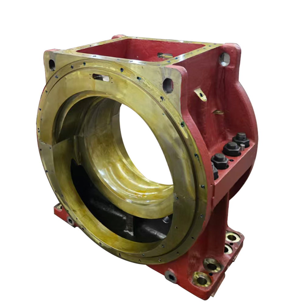
Bearing inspection should include more than surface appearance. Fit, clearance, lubrication passages, support condition, and shaft journal geometry need to be considered together. The intermediate shaft bearing works together with the shaft journal, bearing structure, and lubrication system, which is why shaft diameter, load condition, dimensional fit, and lubrication requirements should be evaluated as connected variables.
Corrective work should remove the excitation source or unfavorable operating condition, not merely suppress the visible symptom. A damaged or unbalanced propeller requires repair and dimensional verification, while excessive shaft runout may require closer examination of straightness, journals, flange interfaces, coupling installation, or shaft replacement depending on the measured condition and allowable limits.
For shaft misalignment vibration, simply moving one bearing until vibration decreases can create unfavorable loads elsewhere. The correction should consider bearing reactions, shaft bending, adjacent equipment alignment, hull condition, and the required hot or operating condition. Alignment-sensitive propulsion arrangements can respond significantly to relatively small changes in bearing position, so shaft alignment should be treated as a system-level engineering task.
Bearing damage requires the same root-cause discipline. Before installing a replacement, confirm journal condition, clearances, lubrication supply, bearing seating, support position, and alignment. If the previous bearing ran hot because it was overloaded or poorly aligned, a new bearing alone will not correct the underlying condition.
Post-repair verification is equally important. Repeat measurements at the same locations and under comparable RPM, load, draft, and temperature conditions used during diagnosis. A lower vibration reading at idle is insufficient evidence if the original problem appeared only after the shaft line warmed up or reached high propulsion load.
For replacement components, purchasing specifications should therefore include more than nominal diameter and material. Shaft drawings, flange geometry, journal dimensions, runout requirements, operating speed, transmitted load, bearing arrangement, inspection requirements, and mating-component information reduce the risk of correcting one component while introducing another geometric incompatibility.
Marine propulsion shaft vibration causes are best diagnosed as a shaft-line system problem rather than by replacing the component closest to the strongest vibration. Speed, load, temperature, location, runout, bearing condition, and alignment should be evaluated together, followed by verification under conditions close to those that produced the original symptom.
Shanghai TOTEM Machinery Co., Ltd. is a manufacturer of large forged and machined shaft-related components. Accurate geometry, interface dimensions, machining control, and inspection requirements remain essential when propulsion shafting parts need to be repaired, replaced, or matched to an existing marine drivetrain.
A: Common causes include propeller excitation, imbalance, shaft runout, misalignment, bearing problems, coupling errors, lubrication issues, and resonance involving the shaft line or supporting structure.
A: A narrow RPM-related peak can indicate resonance, shaft whirling, rotating excitation, or structural amplification. Measurements above and below the affected speed help distinguish these mechanisms.
A: Yes. Thermal growth, changing bearing reactions, machinery movement, and structural conditions can alter running alignment, so cold static measurements may not reproduce the operating condition.
A: No. High temperature can also result from abnormal bearing loading, unsuitable clearance, lubrication problems, journal condition, or shaft alignment that concentrates load within the bearing.
A: Confirm shaft drawings, journal and flange dimensions, runout requirements, operating speed, load, bearing arrangement, mating interfaces, material requirements, and specified inspection and acceptance criteria.


