
Views: 0 Author: Site Editor Publish Time: 2026-07-12 Origin: Site
Unscheduled dry-docking paralyzes commercial shipping operations almost instantly. Sudden mechanical failures often stem from mismatched or improperly maintained components hidden deep inside the hull. You lose significant revenue every hour your vessel sits idle awaiting emergency repairs. Many industry outsiders and novice operators misunderstand the mechanical chain of a vessel's drivetrain. Laypersons frequently confuse the specific roles of various drivetrain segments, assuming all rotating steel cylinders perform identical tasks.
However, the thrust shaft and propeller shaft endure entirely different stress profiles. They demand highly specialized maintenance approaches to prevent catastrophic breakdowns at sea. You must distinguish between these roles to maintain a reliable, seaworthy vessel.
You need a clear understanding of these engineering realities. This guide provides a detailed technical breakdown of the forces acting on your driveline. You will learn about precise material requirements tailored for different harsh operational environments. We also explore robust procurement evaluation criteria. You will discover exactly how to assess these crucial parts, ensuring your next refit maximizes long-term reliability.
Distinct Force Management: The thrust shaft handles axial loads (pushing the ship forward), while the propeller shaft handles torsional loads (rotational torque) and bending stress.
Location in the Drivetrain: The marine thrust shaft connects directly to the main engine or gearbox, whereas the propeller shaft (tail shaft) is the final component extending through the hull to the propeller.
Component Dependencies: Thrust shafts rely heavily on the thrust bearing to transfer vessel propulsion to the hull; propeller shafts rely on stern tube bearings and seals to prevent water ingress.
Compliance & Procurement: Both components require strict adherence to classification society standards (e.g., ABS, DNV, Lloyd's Register) and require different non-destructive testing (NDT) regimens during maintenance.
Understanding the standard mechanical chain from the engine room to the stern provides crucial context. A vessel's driveline is not a single unified rod. It consists of multiple engineered segments working in unison. Sourcing high-quality Marine Propulsion System Parts ensures these separate components integrate smoothly. Each segment targets a specific mechanical function, allowing engineers to isolate forces and simplify maintenance procedures.
This component occupies a highly protected position within the engine room. You will find it positioned immediately aft of the main engine or reduction gear. It acts as the primary bridge between the power generation system and the rest of the drivetrain.
Its primary role involves intercepting the axial thrust generated by the spinning propeller. As the propeller pushes water backwards, it generates a massive forward force. This forward force travels up the driveline. The thrust shaft absorbs this intense kinetic energy and transfers it directly to the ship's hull via the thrust block. Without this dedicated component, the forward pushing force would smash directly into the engine's delicate crankshaft.
The tail shaft sits at the extreme outboard end of the shaft line. It represents the final mechanical link in your vessel's propulsion chain. Unlike internal components, this section leaves the dry environment of the engine room and enters the harsh ocean.
It passes directly through the stern tube, which requires specialized sealing systems to keep seawater out and lubricating oil in. Furthermore, it supports the sheer physical weight of the propeller itself. This creates a challenging cantilevered load. The tail shaft spins rapidly while suspended partially outside the ship, demanding exceptional structural integrity.
You must understand the exact physical stresses each part endures. These engineering realities dictate their specific failure modes and expected lifespans. We can categorize these forces into pushing, twisting, and bending actions.
| Stress Parameter | Thrust Shaft | Propeller Shaft (Tail Shaft) |
|---|---|---|
| Primary Load Type | Axial (Compressive & Tensile) | Torsional (Rotational Twisting) |
| Bending Stress | Minimal (Fully supported inboard) | High (Cantilevered propeller weight) |
| Environmental Exposure | Engine room interior (Oil lubricated) | Seawater, marine growth, hydrodynamic wake |
| Primary Failure Mode | Collar scoring from bearing failure | Corrosion fatigue, seal damage, keyway cracking |
This segment remains subject to extreme compressive and tensile axial forces. When the ship moves forward, the shaft experiences intense compression. When the vessel reverses, the stress flips into heavy tension, pulling against the engine room mounts. These alternating forces dictate strict metallurgical requirements.
You will notice minimal bending stress here because the component sits securely inside the rigid engine room structure. However, it carries a high vulnerability if the bearing clearance is incorrectly calibrated. Even a millimeter of excess clearance allows a hammering effect, which rapidly destroys the integral collar.
The Propeller Shaft faces a completely different mechanical reality. It is subjected to continuous torsional stress from the engine. The engine tries to twist the metal in one direction, while the heavy density of seawater resists the propeller blades in the opposite direction. This constant twisting fatigues standard metals quickly.
Additionally, it endures high radial loads and massive bending moments. The propeller acts as a heavy weight hanging off the end of the vessel. Hydrodynamic wake fields also create uneven pressure across the propeller blades during each rotation. This uneven pressure bends the shaft slightly millions of times per voyage, introducing severe fatigue risks.
Procurement managers and marine engineers need a stringent evaluation criteria framework for selecting these components. You must match metallurgical properties to specific operating environments to ensure longevity.
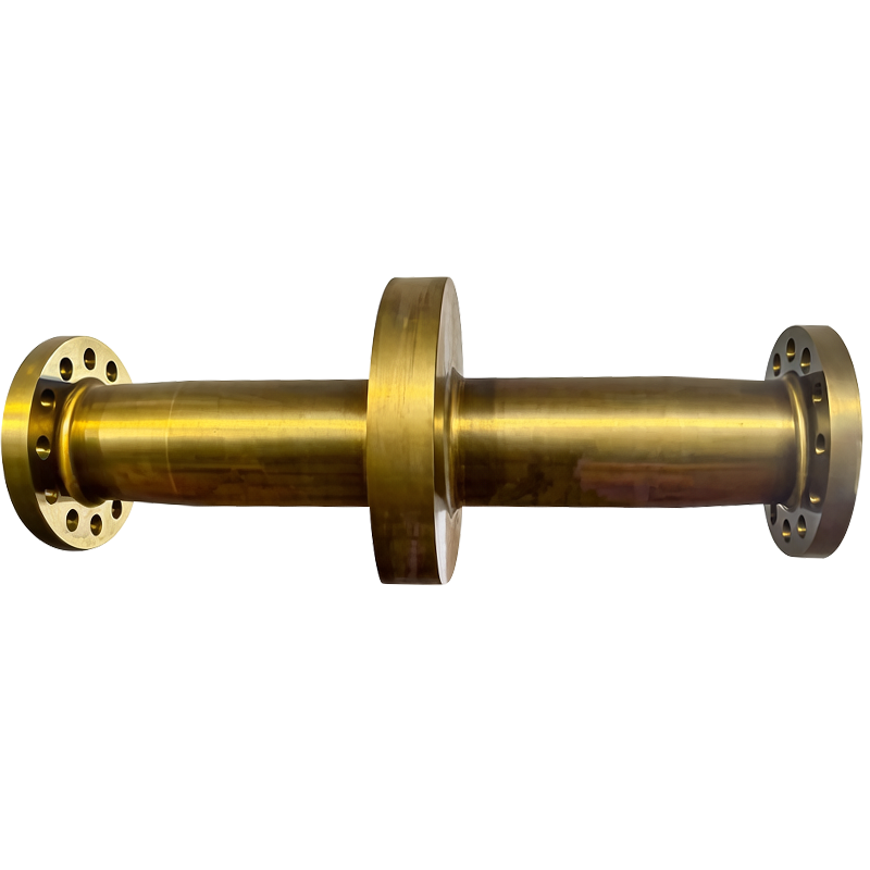
A reliable Marine Thrust Shaft requires exceptional compressive strength. Manufacturers typically forge them from high-tensile carbon steel or specialized alloy steel. The forging process aligns the grain structure of the metal to resist axial compression perfectly.
The most defining design feature is its integral forged collar. This raised ring of solid steel interfaces seamlessly with the thrust pads. Engineers design this collar to distribute the immense pushing force evenly. If a manufacturer attempts to weld a collar onto a straight cylinder rather than forging it as a single piece, catastrophic shearing failures often follow.
This component demands superior corrosion resistance due to continuous seawater exposure. Saltwater acts as a highly aggressive electrolyte, rapidly degrading standard steel. Consequently, manufacturers often construct them from premium duplex stainless steel or nickel-aluminum bronze for smaller vessels.
If engineers specify carbon steel to reduce material costs, they must fit the shaft with bronze or fiberglass liners. These continuous liners physically block seawater from touching the vulnerable steel core. Furthermore, the tapered end design requires incredibly precise machining. The taper must perfectly match the internal hub of the propeller to guarantee maximum friction and torque transfer.
Best Practice: Always request a bluing fit test during installation to ensure the propeller hub mates with the taper at over 80% contact area.
Common Mistake: Ignoring minor liner damage during inspections, which allows localized galvanic corrosion to silently eat away the structural core.
We cannot discuss axial load management without explaining the critical intermediary component. The Thrust Bearing is the unsung hero of the entire Marine Shaft System. It takes the kinetic energy from the spinning collar and securely transfers it to the rigid hull framework.
This component relies strictly on hydrodynamic lubrication principles to survive. Most commercial vessels utilize Michell-type tilting pad bearings. As the collar spins, it drags high-viscosity oil over these pivoting metal pads. The fluid dynamics create a microscopic, highly pressurized wedge of oil. This oil wedge physically separates the spinning steel collar from the stationary pads. It entirely prevents metal-to-metal contact, allowing thousands of tons of pushing force to transmit through a thin layer of fluid.
You must evaluate this area closely during routine checks. Bearing failure directly damages the metal collar. If the oil film breaks down, friction spikes instantly. The babbitt metal lining melts in seconds. Once the bearing collapses, catastrophic axial loads transfer directly into the main engine crankshaft. This scenario often bends engine connecting rods and cracks engine blocks, resulting in multi-million dollar repair bills.
Vessel operators face strict implementation realities. You must adhere to rigid maintenance schedules and class society compliance requirements. Organizations like ABS, DNV, and Lloyd's Register mandate specific evaluation timelines to maintain insurance validity.
Engine Room Checks: Engineers focus intensely on collar scoring. They perform regular bearing clearance checks to ensure the oil wedge can form correctly.
Ultrasonic Flaw Detection: Technicians use ultrasonic testing (UT) to scan deep inside the forgings. This detects internal metallurgical flaws or hidden fatigue cracks before they reach the surface.
Tail Shaft Surveys: Class societies generally require a complete tail shaft withdrawal every five years. Surveyors focus on wear down at the stern tube bearing and verify the integrity of the sealing rings.
Magnetic Particle Inspection (MPI): Technicians apply MPI specifically at the keyway or taper base. These areas represent high-stress concentration zones where micro-cracks typically originate.
You must prepare for two distinct types of failure. A seal failure at the stern tube allows high-pressure water ingress. This washes away crucial lubricating oil, leading to rapid bearing wipedown and potential flooding. It also accelerates galvanic corrosion across the taper.
Conversely, inboard components face lubrication starvation risks. A clogged oil filter or a failed lube oil pump leads to immediate overheating. Without the protective oil wedge, the friction between the collar and pads generates enough heat to trigger engine room fires and permanently warp heavy steel forgings.
Procurement managers need a reliable decision framework when evaluating vendors for heavy marine forgings. A cheap replacement part often costs exponentially more in unplanned downtime.
First, evaluate forging capabilities carefully. Look for facilities utilizing continuous grain flow techniques. This method ensures the molecular structure of the steel follows the physical shape of the collar and flanges. Standard machining, where a vendor simply cuts away material from a large straight block, leaves the grain structure exposed and vulnerable to shear forces.
Next, verify testing transparency. You should only short-list vendors offering comprehensive NDT reports alongside every delivery. Demand material certificates conforming strictly to EN 10204 3.2 standards. This specific certification guarantees an independent class society surveyor witnessed the material testing and confirmed the chemical composition.
Finally, assess lead time and logistical scalability. Ask vendors about their machining tolerances for custom retrofits versus standard vessel class designs. When repairing older vessels, factory-standard dimensions rarely fit perfectly. A capable manufacturer must offer micro-tolerance adjustments to accommodate hull warping and bearing wear.
While both components function as critical propulsion elements, confusing their load requirements inevitably leads to catastrophic system failure. You now understand that axial compression and torsional twisting demand completely distinct engineering solutions. Proper material selection, strict adherence to lubrication protocols, and rigorous non-destructive testing form the bedrock of reliable vessel operations.
Take immediate action to protect your drivetrain. Review your vessel's specific maintenance logs to verify the last tail shaft withdrawal date. Consult with a certified marine metallurgist if you suspect galvanic corrosion near your stern tube. Finally, request a comprehensive technical audit of your shaftline components from a qualified forging manufacturer before your next scheduled dry-docking.
A: On very small recreational vessels like speedboats, the shaft line might be a single, unified rod. However, commercial ships require segmented shafts. This separation accommodates extreme installation logistics, hull flexing, and the necessity of managing massive axial and torsional loads independently.
A: Collar failures almost always result from severe lubrication breakdown in the bearing assembly. Contaminated oil, clogged filters, or severe misalignment of the driveline destroys the protective hydrodynamic oil wedge, causing instantaneous metal-to-metal friction and thermal damage.
A: The taper provides a mechanically secure interference fit. Paired with a keyway or a keyless hydraulic pressure system, the tapered design physically locks the heavy propeller hub in place. This guarantees it can handle immense rotational torque without slipping or wobbling.
A: Standard IACS guidelines typically align comprehensive NDT with the 5-year special survey cycle during dry-docking. However, you must order immediate, out-of-cycle testing if the vessel experiences severe vibration anomalies, propeller strikes, or grounding incidents.


