
Views: 0 Author: Site Editor Publish Time: 2026-08-16 Origin: Site
Gland steam leakage is rarely just a minor maintenance nuisance. It poses a direct threat to plant thermal efficiency. It also jeopardizes rotor dynamic stability. Compromised sealing directly undermines the internal pressure differential. It frequently leads to severe steam blow-out. When this happens, you lose critical working fluid. Alternatively, it allows dangerous air ingress. This destroys the vacuum inside your condensers. We wrote this article to give maintenance engineers and plant managers a practical framework. You will learn how to accurately diagnose steam turbine gland packing leakage causes. We also provide an evidence-based approach to evaluate corrective actions. By the end, you will know exactly how to restore operational integrity during your next planned outage.
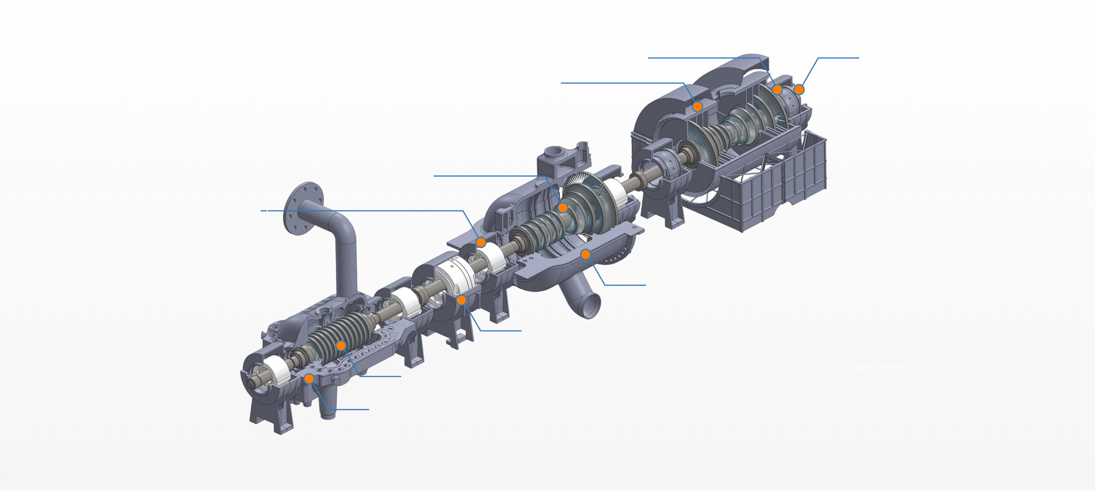
Unchecked gland packing leakage accelerates degradation of the steam turbine rotor shaft and reduces overall megawatt output.
The primary steam turbine gland packing leakage causes range from thermal distortion and rubbing to prolonged abrasive wear.
Effective inspection requires combining visual casing checks with real-time vibration and temperature data analysis.
Decision-makers must evaluate corrective actions by weighing the ROI of routine packing replacement against retrofitting with advanced sealing systems.
Every drop of leaking steam represents wasted energy. We must frame this business problem accurately. When steam escapes, you face immediate make-up water costs. You also suffer lost thermal efficiency. Your overall heat rate increases significantly. Plant managers feel this financial drain daily. You burn more fuel to generate the exact same megawatts.
Beyond finances, we face severe equipment risks. Steam blowing past seals often finds its way into bearing housings. This causes dangerous water ingress into bearing oil. Lube oil contamination rapidly degrades bearing life. It destroys the hydrodynamic film protecting your journals. Furthermore, localized heating from escaping steam causes rotor bowing. This thermal distortion induces severe vibration problems. It can easily force an emergency turbine trip.
What does a successful resolution look like? We establish clear success criteria.
Restored seal pressure matching the original OEM baselines.
Zero visible steam blow-by during full-load operation.
Acceptable vibration signatures across all bearing sensors.
Full compliance with environmental and plant safety standards.
Achieving these criteria requires pinpointing the exact leakage source before commencing repairs.
Identifying the root cause dictates your repair strategy. Let us examine the most common failure modes.
Natural wear happens over countless operating cycles. Solid particle erosion plays a huge role here. Boiler tubes frequently exfoliate microscopic scale particles. High-velocity steam carries these abrasive elements directly into the turbine. They act like sandblasters. They severely damage the seal teeth. They also erode the packing material itself. You will notice increased clearance dimensions over time. This widening directly increases steam blow-by. The labyrinth effect loses its throttling capability entirely.
Power plants often cycle their loads based on grid demand. Rapid start-ups and quick shutdowns create intense thermal stress. Load changes cause rapid differential expansion. The stationary casing heats at a significantly different rate than the heavier rotating components. This thermal mismatch creates severe hard rubbing. The Steam Turbine Rotor Shaft forcefully contacts the delicate seal teeth during these transitional phases. Such friction permanently alters seal clearances. It flattens the sharp labyrinth profile designed to restrict flow. Once flattened, the seal loses its necessary pressure-dropping capability.
We cannot ignore maintenance-induced failures. Outage teams sometimes set incorrect clearance tolerances. They might mistakenly leave debris inside the seal tracks. These simple mistakes ruin otherwise perfectly healthy components.
We also see frequent spring failures. Flat or leaf springs sit behind the packing rings. They maintain proper radial tension against the shaft. Prolonged exposure to superheated steam weakens these springs. They lose their metallurgical temper. When springs relax, the packing rings drift outward. They fail to hug the rotor closely.
Sometimes the seals themselves remain perfectly fine. Apparent packing leakage frequently acts as a symptom of other issues. A blocked gland exhauster forces leak-off steam outward. Insufficient vacuum in the gland steam condenser creates severe back-pressure. When the system cannot pull leak-off steam away, it escapes into the turbine hall. Always verify your exhaust system vacuum before tearing apart the turbine casing.

Accurate diagnosis prevents unnecessary tear-downs. We need a reliable framework.
You must identify early lead indicators before they escalate. Listen for increased acoustic noise near the shaft ends. Look for visible steam plumes escaping the HP/IP/LP Turbine Casing. Monitor your control screens for sudden changes in rotor vibration parameters.
Evaluate pressure differentials closely. The gland sealing header should maintain specific steady pressures. If the required header pressure suddenly drops, you likely have widened internal clearances. Log these data points continuously. Compare them against your known commissioning baselines.
Outages provide the perfect opportunity for deep physical checks. When you remove the casing, begin a strict visual inspection. Look closely at the Steam Turbine Gland Packing rings. Search for heavy scoring or severe carbon buildup. Mushrooming on the seal teeth clearly indicates hard rubbing.
Next, measure your actual clearances. Use precision feeler gauges. Lead wire checks offer excellent accuracy during casing reassembly. Compare all radial and axial measurements against the OEM manual.
Finally, test the backing springs. Check their structural integrity. Measure their radial tension. Replace any spring showing signs of relaxation or high-temperature brittleness.
| Inspection Type | Target Component | Key Defect Indicators |
|---|---|---|
| Visual Inspection | Seal Teeth & Rings | Mushrooming, deep scoring, carbon deposits, discoloration. |
| Clearance Measurement | Radial & Axial Gaps | Measurements exceeding OEM maximum allowable tolerances. |
| Spring Tension Test | Backing Leaf Springs | Loss of temper, cracks, failure to maintain ring position. |
| Track Inspection | Casing Grooves | Debris buildup, steam washing, groove distortion. |
Once you pinpoint the damage, you must choose a repair path. We break down the available options during an outage.
Many generating plants choose the traditional route during outages. They replace worn teeth and packing rings directly. They order exact OEM-spec components from their established supply chain.
This implementation reality feels highly familiar to maintenance crews. It carries the lowest upfront material cost. Installation requires no new training for your mechanics. Outage schedules accommodate this standard work easily.
However, it has notable technical drawbacks. These exact-match components remain completely vulnerable. They will likely suffer the exact same historic wear patterns. If your plant cycles frequently, exact OEM parts might degrade rapidly again. You essentially reset the clock on an inevitable failure.
You might consider advanced mechanical upgrades instead. Let us compare traditional labyrinth seals against newer engineered alternatives. Retractable gland seals and brush seals offer distinct operational advantages.
Traditional carbon packing rubs heavily during low-speed startup. Retractable seals utilize springs to pull away from the shaft during low-speed rolling. They only close the clearance when internal steam pressure rises sufficiently to push them into place. Brush seals use thousands of flexible metal bristles. These bristles conform tightly to the shaft without causing permanent metal-to-metal damage.
This brings us to ROI justification. Retractable seals minimize destructive startup rubbing. They extend your Mean Time Between Failures (MTBF) significantly. They sustain unit thermal efficiency over a much longer operational lifecycle.
You must also weigh the associated risks. These advanced systems require a higher upfront capital expense. They demand precision engineering for proper integration. Retrofitting older distorted casings takes specialized industry knowledge. You must evaluate if your specific operating profile justifies this long-term capital investment.
Your repair is only as good as your replacement components. Choosing the right vendor matters immensely.
Set strict criteria for selecting a vendor. They must specialize in turbomachinery. They must supply premium Steam Turbine Parts. Request specific case studies of their previous seal replacements. Validate their track record with plants similar to yours.
Never skip material verification. Demand thorough metallurgical testing. High-chrome alloys provide vital oxidation resistance. Inferior metals warp under severe heat. Ask your vendor for material certificates before accepting any shipment. You must guarantee structural integrity under extreme thermal loads.
Off-the-shelf parts rarely fit perfectly into older, distorted casings. Buyers should demand advanced engineering capabilities. Look for vendors who offer comprehensive reverse engineering services. They should provide custom clearance modeling. Custom parts account for casing distortion. This guarantees a perfect fit upon installation.
Do not wait until the outage begins. Schedule a pre-outage seal audit today. Arrange a comprehensive dimensional inspection. Early planning prevents costly delays when the turbine casing finally opens.
Contact turbomachinery experts for a pre-outage consultation.
Conduct an online acoustic and vibration audit while the unit runs.
Pre-order custom-engineered sealing rings based on historical distortion data.
Finalize the outage execution schedule for efficient casing removal.
Understanding exact steam turbine gland packing leakage causes remains critical. It provides the only reliable way to prevent recurrent failures. Moving away from reactive repairs offers immense value. Engineered sealing upgrades deliver the best long-term protection. They safeguard the turbine rotor and preserve the casing integrity.
Consult with turbomachinery experts immediately. Request a technical seal evaluation before your next scheduled major outage. Proactive diagnostics will save your plant significant downtime. It will protect your valuable rotating equipment from permanent damage.
A: Acceptable clearances vary significantly by OEM specifications. They depend heavily on the rotor diameter. The section location also matters greatly. An HP section requires different tolerances than an IP or LP section. You must consult your specific turbine technical manual to find the exact required dimensions.
A: A faulty exhauster fails to maintain a slight vacuum. This vacuum normally draws off the leak-off steam. Without it, back-pressure builds up rapidly. This pressure forces steam outward past the seals. It looks exactly like severe packing leakage, even when internal clearances remain perfectly correct.
A: They are absolutely worth it for cycling units. Plants with frequent start-stop cycles experience chronic rubbing. Retractable seals eliminate this friction entirely. However, they might be over-engineered for baseload units. Turbines with highly stable thermal profiles often run perfectly fine on traditional, well-maintained labyrinth packing.
A: Yes, it frequently causes severe vibration. Localized steam leaks create uneven thermal distribution across the shaft. This uneven heating causes the massive rotor shaft to bow. A bowed rotor immediately generates high 1X vibration signatures, which can trip the turbine if left unresolved.


