Please Choose Your Language
Views: 0 Author: Site Editor Publish Time: 2026-10-28 Origin: Site
A turbine shaft must transmit power while resisting deformation and maintaining reliable rotor behavior. Power and rotational speed establish transmitted torque, but torque alone cannot define the finished shaft. An initial diameter must satisfy both allowable shear stress and torsional twist before engineers examine bending, fatigue, temperature, and rotor dynamics. The practical starting point is therefore a pair of calculations: one for strength and another for stiffness. The method below applies to an ideal solid circular shaft under elastic torsion. It provides a preliminary engineering estimate, not a complete steam turbine rotor design procedure or a manufacturing release dimension.
Diameter strongly affects torque capacity and resistance to twisting. For a solid circular section, torsional shear stress varies inversely with diameter cubed, while twist varies inversely with diameter to the fourth power. A modest dimensional change can therefore have a substantial effect.
An undersized turbine shaft can exceed its stress limit, twist excessively, or create unacceptable interface behavior. Increasing diameter reduces these nominal torsional demands, but it also adds material, changes mass distribution, affects bearing and coupling interfaces, and alters the rotor's dynamic properties. More material is not automatically a better system design.
The useful question is which requirement controls each shaft section. A journal, coupling seat, and rotor body do not necessarily carry identical loads or need identical diameters. Preliminary calculations should support a stepped shaft layout rather than encourage one oversized dimension along the entire rotor.
Calculate torque from the mechanical power transmitted through the section and its rotational speed. Use shaft output power, not steam thermal input or generator electrical output without the necessary efficiency and drivetrain adjustments.
T = 9550P / n
T: transmitted torque in N·m.
P: mechanical power in kW.
n: rotational speed in rpm.
The factor 9550 is rounded from 60,000/(2π). It follows from P = Tω, with power in watts and angular velocity ω = 2πn/60 in radians per second. Do not insert watts into the kW version of the equation.
All values in this example are illustrative assumptions. They are not specifications for an actual steam turbine. Assume a uniform solid shaft transmits 1,000 kW at 3,000 rpm:
T = 9550 × 1000 / 3000 ≈ 3183 N·m
At the same power and 1,500 rpm, torque would approximately double to 6,367 N·m. Under unchanged allowable shear stress, the strength-based diameter would increase by the cube root of two, or about 26%. This illustrates why lower-speed transmission can require a larger turbine shaft.
The equation describes steady power transmission. Startup, trips, load rejection, and other transients require their own torque assessment. Dividing rated power by a speed approaching zero is not a valid way to obtain startup torque; the actual operating load case must be established.
For a solid circular shaft under pure, linear-elastic torsion, the maximum nominal shear stress occurs at the outer surface. Using the polar second moment of area J = πd4/32 gives:
τmax = 16T / (πd3)
dstress = [16T / (πτallow)]1/3
Keep units consistent. With torque in N·m and allowable stress in Pa, diameter is in metres. Alternatively, use torque in N·mm and stress in MPa, equivalent to N/mm², to obtain diameter directly in millimetres.
For the example, assume an allowable shear stress of 40 MPa purely to demonstrate the calculation:
dstress = [16 × 3183 / (π × 40 × 106)]1/3
dstress ≈ 0.0740 m = 74.0 mm
This is an idealized torsional strength estimate. It excludes bending, fatigue, stress concentrations, thermal effects, and rotor dynamics. It cannot be used as the final turbine shaft diameter.
Allowable shear stress must reflect the specified material condition, operating temperature, relevant failure mode, design basis, and required margins. The assumed 40 MPa is neither a universal steel value nor a recommended turbine design limit.
Also define how margins are applied. If allowable stress already includes a safety factor, an additional factor should not be inserted without understanding the design method. A load multiplier acts inside the cube-root diameter equation; multiplying the calculated diameter by that same number produces a different margin. Documenting this distinction makes the calculation reviewable.
For a bored rotor, replace the solid-section expression with J = π(do4 − di4)/32 and τmax = Tdo/(2J). The bore removes material and changes both stress and stiffness. The solid-shaft result should not be transferred unchanged.
A turbine shaft can pass the shear-stress check and still twist too much. For a uniform solid circular segment with constant torque, length, and shear modulus:
θ = TL/(GJ) = 32TL/(πGd4)
dtwist = [32TL/(πGθallow)]1/4
Here θ is relative angular displacement in radians, L is segment length, and G is material shear modulus. Use metres and Pa with torque in N·m, or millimetres and N/mm² with torque in N·mm. Convert a degree limit to radians using θrad = θdegπ/180.
Add three illustrative assumptions: segment length L = 1.0 m, shear modulus G = 80 GPa, and allowable total twist θallow = 0.5° across that segment. These are calculation inputs, not turbine acceptance criteria.
θ at d = 74.0 mm
= 32 × 3183 × 1.0 / [π × 80 × 109 × (0.0740)4]
≈ 0.0135 rad ≈ 0.775°
The 74.0 mm section fails the assumed twist limit even though it meets the nominal shear-stress limit. Solving for the stiffness-based diameter gives approximately 82.6 mm. Taking the larger preliminary requirement therefore gives 82.6 mm before other checks and dimensional detailing.
Illustrative trial diameter | Nominal shear stress | Total twist over 1 m | Result against assumed limits |
|---|---|---|---|
74.0 mm | About 40.0 MPa | About 0.775° | Twist governs; insufficient stiffness |
82.6 mm | About 28.8 MPa | About 0.499° | Meets these two illustrative checks only |
For a stepped turbine shaft, calculate twist for each segment and sum the signed contributions: θ = Σ[TiLi/(GiJi)]. Use the torque actually transmitted through each segment. Treating a long, narrow coupling section as part of a uniform large rotor body can underestimate total twist.
The larger torsional estimate is a starting geometry, not a release decision. A real turbine shaft requires checks of the complete loading history, local features, support arrangement, and operating environment.
Combined loading: Rotor weight, steam forces, coupling loads, and alignment conditions can introduce bending and axial loading alongside torque.
Fatigue: Rotating bending and repeated operating cycles require assessment of alternating and mean stress, material condition, surface condition, and local geometry.
Stress concentrations: Shoulders, fillets, grooves, keyways, and coupling connections can govern locally even when nominal stress is acceptable.
Material and temperature: Use properties appropriate to the specified heat treatment and service temperature; assess time-dependent behavior where relevant.
Supports and dynamics: Bearing span, bearing properties, rotor mass, and shaft stiffness influence deflection, modes, and critical-speed response.
Thermal conditions: Temperature gradients, expansion, and thermal bow require consideration in the rotor and clearance design.
For each critical section, record the load case, calculation basis, applicable limit, and remaining verification. This prevents a preliminary torque calculation from being mistaken for evidence that the complete rotor is acceptable.
Convert the validated design into an approved drawing and inspection plan. Material grade, heat treatment, forging acceptance, journal dimensions, datum relationships, and surface texture must be specified together; a diameter tolerance alone does not describe a functional turbine shaft.
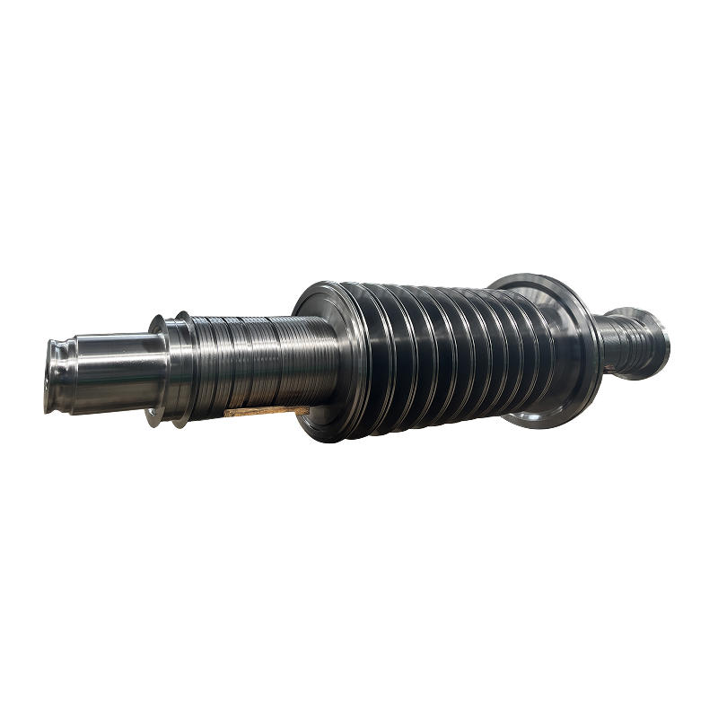
Shanghai TOTEM Machinery Co., Ltd. is a manufacturer and supplier offering drawing-based machining and forged steam turbine rotor shafts with ultrasonic testing. Its machining capabilities include turning, milling, and grinding. These capabilities support production to defined requirements; the rotor design authority still needs to establish and approve the full mechanical and dynamic design.
A useful manufacturing handover identifies material traceability and heat-treatment records, required forging examinations, journal size and form, coaxial relationships, datum-based runout, and surface roughness. Define acceptance limits and measurement conditions rather than relying on general terms such as precision.
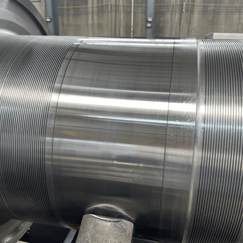
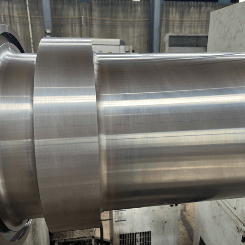
Inspection should distinguish roundness from runout and dimensional conformance from balance. A journal can meet its nominal diameter while failing a geometric requirement. The relevant turbine part quality checks should therefore follow the approved component function and drawing revision.
Begin turbine shaft sizing by calculating torque from mechanical power and speed, then compare the diameters required by allowable shear stress and allowable twist. In the illustrative example, stiffness raises the preliminary requirement from about 74.0 mm to 82.6 mm. Neither result establishes the finished rotor size. Combined loads, fatigue, temperature, local geometry, and rotor dynamics remain essential design checks. Shanghai TOTEM Machinery Co., Ltd., a manufacturer and supplier of machined components, can support drawing-based shaft production. Manufacturing requirements should follow the approved design and inspection plan so that the finished component can be assessed against explicit criteria.
At fixed speed, torque rises in proportion to mechanical power. With unchanged allowable shear stress, the ideal strength-based diameter scales with power to the one-third power. With unchanged length, shear modulus, and allowable twist, the stiffness-based diameter scales with power to the one-fourth power.
No. Higher speed reduces steady torque at fixed power, which can lower a torque-only estimate. The final diameter may still be controlled by rotor dynamics, bending, fatigue, interfaces, or transient loads. Speed must be evaluated within the complete rotor design.
Strength concerns whether stress remains within the chosen material and design limits. Torsional stiffness concerns how much one section rotates relative to another under torque. Increasing material strength does not necessarily produce a comparable increase in shear modulus or reduce twist.
No. Torque establishes only part of the loading. A final design also needs the shaft geometry, support arrangement, bending and axial loads, operating cycles, temperature conditions, interfaces, and rotor dynamic requirements.