
Views: 0 Author: Site Editor Publish Time: 2026-06-17 Origin: Site
Marine propulsion system shafting is the core component of a ship's power plant. As an essential power link, it transmits output power from the main engine to the propeller, and meanwhile channels the generated thrust from the propeller to the vessel. The operational condition of these vital marine propulsion system parts has a decisive impact on a vessel's propulsion efficiency, navigational safety, as well as the cost-effectiveness within its lifecycle.
With International Maritime Organization (IMO) decarbonization rules such as EEXI and CII broadly enforced, and digitalization advancing quickly across shipping industry, marine propulsion system technologies are entering a major transition. Vessel propulsion is moving beyond conventional mechanical power transfer, towards greener, smarter, and more lightweight solutions.
New technical developments continue to appear, opening fresh options for more efficient shafting design. Key advancements include:
l Advanced Materials: The application of carbon fiber composites and engineering ceramics.
l Novel Structures: Innovative configurations like the Sterntubeless design.
l Next-Generation Monitoring: The deployment of digital twin technology and fiber-optic sensing.
This article is a systematic review of essential principles as well as latest developments in shafting, helping engineering designers and technical leaders access a reliable, in-depth resource for informed sourcing and specification decisions. Key topics include:
l Core design theories of the marine propulsion system
l Functions and optimization of critical marine propulsion system parts
l Integration of new material applications
l Advanced vibration control methodologies
l Intelligent monitoring and frontier development trends
A typical marine propulsion system shafting consists of the following key components:
No. | Component | Function Description |
1 | Transmits axial thrust generated by the propeller to the hull via the thrust bearing | |
2 | Connects the thrust shaft to the stern shaft; multiple sections may be used depending on engine room layout | |
3 | Connects the intermediate shaft to the propeller; passes through the stern tube and withstands maximum bending moments | |
4 | Thrust Bearing | Absorbs axial thrust; typically a Michell-type sliding thrust bearing |
5 | Intermediate Bearing | Supports the intermediate shaft and withstands radial loads |
6 | Stern Tube Bearing | Supports the stern shaft underwater under the harshest operating conditions |
7 | Coupling | Connects shaft sections, transmits torque, and compensates for minor installation misalignment |
8 | Bulkhead Stuffing Box | Ensures watertight integrity between compartments, preventing water leakage |
9 | Stern Tube Seal | Prevents seawater ingress into the stern tube and oil leakage from the lubrication system |
The design of a marine propulsion system shafting is a multidisciplinary systems engineering process. The standard workflow includes:
1.Engine & Propeller Selection – Determine rated power, rotational speed, and gearbox reduction ratio
2.Preliminary Shaft Diameter Estimation – Use classification society empirical formulas for initial sizing
3.Material Selection – Balance strength, fatigue performance, corrosion resistance, and cost
4.Shafting Layout & Bearing Positioning – Establish axial positions and support configurations
5.Static Strength Verification – Stress analysis and safety factor calculations
6.Vibration Analysis – Torsional, lateral (whirling), and longitudinal vibration assessment
7.Shafting Alignment Calculation – Determine optimal bearing offsets to ensure bearing loads remain within allowable limits
8.Fatigue Strength Assessment – Evaluate fatigue life under alternating loads
9.Detailed Design & Component Sourcing – Finalize construction drawings and technical specifications
· Static Loading – Bending stress, shear stress, and bearing specific pressure verification
· Dynamic Loading – Torsional vibration, lateral vibration, longitudinal vibration, and shafting alignment analysis
· Fatigue Behavior – Fatigue life prediction and crack propagation assessment under cyclic loading
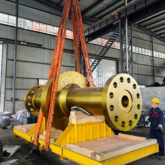
Shafting alignment is the most critical factor ensuring safe and stable operation of a marine propulsion system. Poor alignment leads to elevated bearing temperatures, abnormal wear, increased vibration, and even shaft fracture.
Evolution of Shafting Alignment Methods:
1st Generation - Straight-Line Alignment: All bearing centers aligned on a straight line — simple but ineffective under hull deformation
2nd Generation - Allowable Load Alignment: Bearing loads adjusted within permissible limits by modifying bearing offsets
3rd Generation - Optimized Alignment: Uses optimization algorithms to determine optimal bearing offsets considering loads, bending stress, bearing angles, and flange openings — now the industry standard
4th Generation - Dynamic Alignment: Accounts for hull deformation, oil film stiffness, thermal effects, and wave loads for full-operating-condition optimization
Key Influencing Factors:
Factor | Mechanism | Countermeasure |
Hull Deformation | Hull deflection from loading/unloading and wave action | Global FEM–shafting coupled analysis |
Bearing Oil Film Stiffness | Film thickness and stiffness vary with operating conditions | Elastohydrodynamic lubrication (EHL) modeling |
Thermal Effects | Thermal expansion alters bearing offsets | Pre-set hot clearance + hot alignment procedure |
Propeller Hydrodynamics | Eccentric thrust generates additional bending moments | Coupled calculation including propeller excitation forces |
Installation Tolerance | On-site construction deviations | Laser alignment technology |
(1) Torsional Vibration
Caused by cyclic combustion pressure in diesel cylinders. Key parameter: torsional vibration additional stress must not exceed classification society limits (typically ±20–30 N/mm²). The barred speed range must avoid normal operating speeds.
Mitigation measures: Torsional vibration dampers (silicone oil / rubber), optimized flywheel inertia, and high-elasticity couplings.
(2) Lateral (Whirling) Vibration
Caused by propeller mass imbalance, hydrodynamic imbalance, and bearing oil film forces. Design criteria: first-order lateral critical speed should exceed 120% of maximum operating speed (rigid shaft design) or fall below 80% of minimum stable speed (flexible shaft design), with properly spaced bearing intervals.
(3) Longitudinal Vibration
Caused by propeller thrust fluctuation in non-uniform wake fields and axial excitation from the diesel engine — particularly prominent in long-shaft vessels. Frontier research directions: thrust bearing–hull coupled dynamics, axial vibration dampers, and active thrust compensation technology.
CFRP drive shafts represent one of the most significant technological innovations in marine propulsion system shafting in recent years.
l Technical Advantages: Compared with traditional alloy steel shafts, CFRP shafts offer:
Density: 1.55–1.75 g/cm³ → 70–78% weight reduction
Specific Strength: ~900 MPa/(g/cm³) → 5–6× higher than alloy steel
Damping Factor: 0.01–0.03 → 10–30× superior to steel
Thermal Expansion: Near-zero (−0.5 to +0.5 ×10⁻⁶/K) → excellent thermal stability
Corrosion Resistance: Natural seawater resistance — no protective coating maintenance required
l Design & Manufacturing: The core technology lies in ply stacking design — optimizing fiber orientation (0°/±45°/90° laminate combinations) to meet torque transmission, bending stiffness, and axial load requirements. A typical manufacturing process combines fiber winding with prepreg layup. The connection between metal flanged joints (titanium alloy or stainless steel) and the CFRP tube body is a critical challenge. Common methods include bonding + mechanical locking, hybrid bonding + bolting, and co-curing integration.
l Current Applications: CFRP shafts have achieved commercial deployment in high-speed naval vessels, luxury yachts, and OSV (Offshore Support Vessels). Market forecasts project a 15%+ CAGR for the global CFRP propeller shaft market in maritime applications.
CFRP vs. Alloy Steel — Marine Propulsion System Parts Comparison:
Property | Alloy Steel Shaft (40CrNi2MoA) | CFRP Drive Shaft | Advantage |
Density (g/cm³) | 7.85 | 1.55–1.75 | 70–78% lighter |
Specific Strength (MPa/(g/cm³)) | ~140 | ~900 | 5–6× higher specific strength |
Specific Modulus (GPa/(g/cm³)) | ~26 | ~80 | ~3× higher specific stiffness |
Damping Factor | 0.001–0.002 | 0.01–0.03 | 10–30× better damping |
Thermal Expansion (10⁻⁶/K) | ~12 | −0.5~+0.5 (tailorable) | Superior thermal stability |
Fatigue Limit / Tensile Strength Ratio | 0.35–0.50 | 0.50–0.70 | Better fatigue performance |
Seawater Corrosion Resistance | Requires coating | Natural resistance | Maintenance-free |
Applying ceramic coatings to stern tube shaft surfaces significantly enhances wear resistance and seawater corrosion resistance — two of the most demanding performance requirements for marine propulsion system parts.
Key Coating Technologies:
Process | Characteristics | Typical Applications |
HVOF (High-Velocity Oxygen Fuel) | High coating density, excellent bonding strength | WC-Co, Cr₃C₂-NiCr coatings |
APS (Atmospheric Plasma Spraying) | Broad material compatibility | Oxide ceramic coatings |
Laser Cladding | Metallurgical bonding, minimal heat distortion | Ni-based/Co-based + ceramic particle composite coatings |
PVD (Physical Vapor Deposition) | Ultra-thin (<5 μm), ultra-high hardness | TiN, CrN hard coatings |
Water-lubricated bearings use water as the lubricating medium, fundamentally eliminating oil contamination — representing a core technology direction for green marine propulsion system shafting.
Water-Lubricated Bearing Materials & Characteristics:
Material | Typical Supplier | Key Features | Limitations |
Lignum Vitae | Traditional material | Natural self-lubrication, excellent seawater compatibility | Scarce resources, unstable supply |
Nitrile Rubber (NBR) | Multiple manufacturers | Low cost, good tolerance to sediment | Prone to heat and wear at high speeds |
Phenolic Resin Composite | Thordon COMPAC | Excellent wear resistance, high load capacity | Requires high machining precision |
PEEK Composite | CIP Composites | Ultra-high wear resistance, outstanding temperature performance | Higher cost |
Thordon (SXL) | Thordon Bearings | Superior self-lubrication and water-lubricated performance | — |
· Sterntubeless Design — A revolutionary concept proposed by the Blue Ocean Alliance: eliminating the traditional stern tube in favor of seawater-lubricated bearings + tapered key connections. Alliance members include ABS, Thordon, SDARI, Wärtsilä, and NTUA.
· Next-Generation Composites — Carbon fiber-reinforced PEEK, graphene-modified polymers, and biomimetic microstructured bearing liners for marine propulsion system parts.
· Digital Twin Monitoring for Water-Lubricated Bearings — Structural health monitoring based on embedded sensors; relevant research was published in Ocean Engineering in 2026.
The primary excitation sources driving marine propulsion system shafting vibration include:
1. Diesel Engine Excitation Forces — Torque pulsation caused by periodic cylinder combustion pressure
2. Propeller Excitation Forces — Thrust and torque pulsation generated by non-uniform wake fields (dominated by blade pass frequency — BPF)
3. Shafting Imbalance Forces — Rotating imbalance from manufacturing and installation tolerances
4. Bearing Oil Film Forces — Self-excited vibration from oil film whirl and oil film oscillation
Control Strategy | Specific Measures | Control Target |
Frequency Tuning | Adjust shaft diameter, segment length, bearing spacing | Critical speeds |
Damping Control | Silicone oil dampers, high-elasticity couplings | Torsional vibration |
Isolation Design | Elastic bulkhead supports, floating raft isolation systems | Structural noise transmission paths |
Active Control | Active thrust compensation, magnetic bearings | Longitudinal vibration |
For naval vessels and research vessels, underwater radiated noise (URN) is a critical tactical and technical performance indicator. Primary control measures include:
· Low-noise propeller design — Reduces propeller cavitation and blade passing frequency noise
· High-damping couplings — Minimizes torsional vibration transmission through the marine propulsion system
· Thrust bearing isolation design — Decouples shafting vibration from the hull structure
· Water-lubricated bearing friction noise suppression — Reduces self-generated noise from bearing surfaces
Modern marine propulsion system condition monitoring encompasses the following critical parameters:
Parameter Category | Specific Parameter | Sensor Type |
Vibration | Bearing housing vibration acceleration / velocity / displacement | Piezoelectric accelerometers |
Temperature | Operating temperature of each bearing | PT100 RTD / thermocouple |
Shaft Power | Shaft torque + speed → power output | Strain gauge / photoelectric shaft power meter |
Oil Condition | Water content, wear particle count and size | Online oil monitoring sensors |
Shaft Position | Shaft center orbit, axial displacement | Eddy current displacement sensors |
Strain | Shaft bending / torsional strain | Strain gauges / Fiber Bragg Grating (FBG) sensors |
A comprehensive marine propulsion system condition monitoring system integrates multi-parameter sensing to provide real-time visibility into shafting health — enabling operators to detect early signs of bearing degradation, misalignment, or overload before critical failure occurs.
Major classification societies have established clear requirements for shafting condition monitoring within marine propulsion system parts:
ClassNK: Vessels equipped with bearing temperature sensors must perform oil analysis every 6 months + monthly water content analysis, or oil analysis every 3 months. Implements PSCM (Propeller Shaft Condition Monitoring) approval framework
DNV: Under TMON (Tailshaft Monitoring) regulations, condition-based monitoring can extend tailshaft withdrawal inspection intervals from the traditional 5 years to a maximum of 15 years
CCS: Published Guidelines for Inspection of Ship Propulsion Shafting Condition Monitoring Systems, providing regulatory framework for Chinese-built vessels
These classification society standards demonstrate the industry’s shift from time-based maintenance toward Condition-Based Maintenance (CBM) for marine propulsion system shafting — reducing downtime while enhancing safety.
The marine propulsion system digital twin technology adopts a four-layer architecture:
· Physical Layer — Real-vessel shafting and sensor networks (FBG fiber optic, vibration, temperature, and oil condition sensors)
· Data Layer — Real-time data acquisition, storage, and preprocessing (edge computing gateways, time-series databases)
· Model Layer — Multi-physics coupled simulation models (FEM + BEM + EHL joint simulation)
· Application Layer — Condition assessment, fault diagnosis, and remaining useful life (RUL) prediction (AI/ML algorithms, Large Language Model inference)
This four-layer digital twin framework enables marine propulsion system operators to create a virtual replica of the physical shafting — continuously updated with real-time sensor data to mirror actual operating conditions, predict failures, and optimize maintenance schedules.
Digital twin technology delivers measurable value across key marine propulsion system maintenance scenarios:
Real-time Alignment Assessment: Continuous evaluation of shafting alignment status under varying operating conditions
Bearing Wear Prediction: Remaining Useful Life (RUL) estimation for water-lubricated and oil-lubricated bearings
CNN/LSTM Fault Recognition: Deep learning-based identification of typical fault patterns — imbalance, misalignment, bearing defect
Condition-Based Maintenance (CBM): Data-driven maintenance decision-making replacing traditional Time-Based Maintenance (TBM)
Emerging Trend — Large Language Models in Structural Health Monitoring (SHM):
A 2025 review in Chinese Journal of Ship Research highlights how large language models (LLMs) are driving a paradigm shift in marine propulsion system structural health monitoring:
· Multi-modal data fusion — Integrating vibration, temperature, oil, and strain data for holistic shafting health assessment
· Zero-shot / few-shot fault transfer learning — Adapting trained models to new vessel configurations with minimal additional data
· Natural language diagnostic reporting — Automatically generating human-readable fault analysis reports from sensor data
· Predictive maintenance intelligent decision support — AI-driven maintenance scheduling optimized for vessel operational profiles
Applicable Vessels: Large bulk carriers, VLCC (Very Large Crude Carriers), large container ships.
Power Transmission Chain:
Low-speed two-stroke diesel engine (50–100 rpm) → Intermediate shaft → Stern shaft → Fixed Pitch Propeller (FPP)
Key Characteristics:
· Shortest transmission chain among all marine propulsion system configurations
· Highest efficiency — transmission efficiency exceeds 98%
· Large shaft diameter — VLCC intermediate shafts can reach 600–800 mm
· Integrated thrust bearing — housed within the main engine body
This configuration remains the dominant choice for large merchant vessels due to its mechanical simplicity and proven reliability in continuous-duty marine propulsion system applications.
Applicable Vessels: Small-to-medium cargo ships, Offshore Support Vessels (OSV), ferries.
Power Transmission Chain:
Medium-speed four-stroke diesel engine (500–1000 rpm) → High-elasticity coupling → Reduction gearbox → Intermediate shaft → Stern shaft → Controllable Pitch Propeller (CPP) / Fixed Pitch Propeller (FPP)
Design Essentials for Marine Propulsion System Parts:
· Complete torsional vibration analysis is mandatory — higher engine speeds introduce complex vibration modes
· High-elasticity coupling selection is critical — isolates torsional excitation from the drivetrain
· Independent thrust bearing is typically configured separately from the gearbox
The medium-speed diesel + gearbox configuration offers greater flexibility in engine room layout and is increasingly adopted in vessels requiring CPP for enhanced maneuverability.
Applicable Vessels: Service Operation Vessels (SOV), Offshore Support Vessels (OSV), research vessels.
Operating Modes:
Mode | Power Flow |
PTO (Power Take-Off) Mechanical | Diesel engine → Gearbox → Shaft generator + propulsion shafting |
PTI (Power Take-In) Electric | Generator sets → Propulsion motor → Gearbox → Shafting |
Pure Electric | Battery bank → Propulsion motor → Shafting |
Design Features of Hybrid Marine Propulsion System Parts:
· Multiple PTO/PTI interfaces requiring sophisticated power management
· Multi-condition alignment and vibration analysis — shafting must perform across mechanical, electric, and hybrid modes
· Reverse torque capability — the shafting must withstand torque reversal during mode transitions
Hybrid propulsion represents a growing segment in the marine propulsion system market, particularly for vessels with dynamic positioning (DP) requirements and frequent harbor maneuvering.
Applicable Vessels: Electric ferries, inland cargo vessels, small sightseeing boats.
Power Transmission Chain:
Battery / Fuel cell → Inverter → Permanent Magnet Synchronous Motor (PMSM) → Direct-drive propeller
Advantages of All-Electric Marine Propulsion System:
· Flexible layout — electric motors can be placed close to the propeller, eliminating long shafting
· Low noise — critical for passenger vessels and research ships
· Zero emissions (pure electric mode) — aligns with IMO 2030/2050 decarbonization targets
Full electric propulsion is a key technology direction for green shipping and is expected to see accelerated adoption in short-sea shipping and inland waterway transport.
For complex hull forms such as multi-shaft destroyers and high-speed catamarans, traditional empirical bearing placement is insufficient. Genetic Algorithms (GA) and Particle Swarm Optimization (PSO) are employed for multi-objective bearing position optimization — minimizing bearing reaction forces while controlling shaft bending stresses.
This advanced bearing optimization methodology has been successfully applied in the design of multiple naval vessel marine propulsion system shafting arrangements.
Over the next 5–10 years, CFRP drive shafts will transition from demonstration applications to large-scale commercial deployment in marine propulsion system parts.
Key Breakthrough Areas:
· Manufacturing processes for large-diameter (>400 mm) CFRP shafts
· Full-life fatigue validation of metal–CFRP joint connections
· Harmonization and completion of classification society design codes for composite shafting
As production costs decrease and certification frameworks mature, CFRP shafts are expected to penetrate mainstream commercial vessel segments beyond high-performance niche applications.
The Blue Ocean Alliance (BOA) has proposed a revolutionary sterntubeless ship design for marine propulsion system shafting:
· Seawater-lubricated bearings replace oil-lubricated stern tube bearings
· Tapered key connections replace traditional stern tube assembly
· Elimination of traditional stern tube, aft seal, and shaft coating
Target Outcomes: Simplified structure, zero oil pollution, and reduced maintenance burden — a truly disruptive advancement for environmentally compliant marine propulsion system design.
Marine propulsion system maintenance is evolving from reactive fault diagnosis to predictive autonomous decision-making.
Core Technologies:
· Large Language Model (LLM)-driven diagnostic reasoning engines — natural language fault interpretation from multi-sensor data
· Federated learning-enabled multi-vessel collaborative models — shared learning across fleets without compromising data privacy
· Adaptive shafting alignment technology — real-time bearing offset adjustment based on operating conditions
These AI technologies will fundamentally transform how marine propulsion system parts are monitored, maintained, and optimized throughout their lifecycle.
High-Temperature Superconducting (HTS) Motors:
· Dramatically reduce propulsion motor volume and weight
· Significantly increase power density — enabling more compact marine propulsion system arrangements
Active Magnetic Bearings (AMB):
· Contact-free, friction-free operation — no mechanical wear
· No lubrication required — eliminates oil systems entirely
· Real-time active control — dynamically adjusts bearing forces to suppress vibration
· Fundamentally eliminates bearing wear and oil film whirl problems in marine propulsion system shafting
Hydrogen fuel cell propulsion will drive profound changes in marine propulsion system shafting technology:
Distributed propulsion - Multiple small propulsion units replace single large-thrust main engines
Rim-driven thruster integrated design - Motor integrated into the propeller hub — no traditional shafting required
Transmission architecture shift - Transition from centralized long shafting to distributed short shafting
Hydrogen-powered marine propulsion system designs will prioritize modularity, compactness, and zero emissions — reshaping both shafting configuration and overall vessel architecture.
[1] Lai Guojun, et al. Research progress on key technologies for scheme design of marine propulsion shafting. Chinese Journal of Ship Research, 2019.
[2] Design research on carbon fiber reinforced polymer composite in marine propulsion shafting of a naval vessel. Ship Science and Technology, 2025.
[3] Structural health monitoring of water-lubricated stern bearing systems based on digital twins[J]. Ocean Engineering, 2026.
[4] Yang Zewen, et al. Review and prospects of key technologies for large model-driven ship structural health monitoring systems. Chinese Journal of Ship Research, 2025.
[5] Optimal arrangement design of the propulsion shafting system for a ship with multiple strut bearings. SSRN Preprint, 2025.
[6] IACS UR M68 – Unified Requirement for Shaft Alignment.
[7] ClassNK. Propeller Shaft Condition Monitoring Systems.
[8] Thordon Bearings. COMPAC Water Lubricated Bearing Systems.
[9] Blue Ocean Alliance. Sterntubeless Ship Design Concept.
[10] CCS. Guidelines for Survey of Marine Propulsion Shafting Condition Monitoring System.


