Views: 0 Author: Site Editor Publish Time: 2026-06-26 Origin: Site
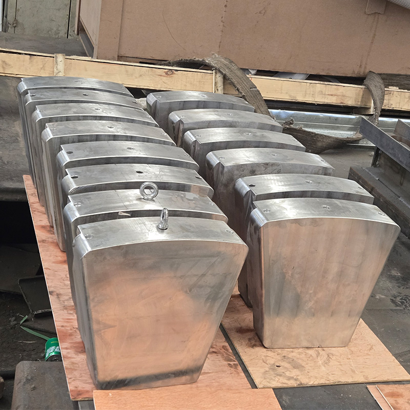
Propulsion downtime costs thousands of dollars per hour. Choosing the right components dictates vessel reliability in high-stakes operational realities. You cannot afford unexpected mechanical failures at sea. The thrust pad bearing serves as the critical failure point. It acts as the primary load-bearing unit in large-scale marine applications. When this component fails, the entire vessel halts. You need an engineering-led framework for evaluating Babbitt alloy configurations. Verifying load ratings ensures long-term operational success. We will explore how to shortlist specifications for heavy-duty marine applications. You will learn the core differences in material performance. We also detail how to properly verify hydrodynamic fluid films. By understanding these mechanical nuances, you can prevent catastrophic failures. This guide provides actionable steps. It helps you evaluate and procure robust thrust components.
Babbitt alloy limitations: Traditional white metal offers unmatched embeddability but requires strict thermal monitoring to prevent wiping under heavy axial loads.
Load rating dependencies: True load capacity relies on hydrodynamic fluid film thickness, not just static material strength.
Tilting pad advantages: Self-aligning pad geometry significantly increases load limits compared to fixed-geometry alternatives.
Procurement criteria: Shortlisting requires vendor verification of ultrasonic bond testing (UT) and centrifugal casting methodologies.
The physics of marine propulsion rely on transferring massive axial thrust. A propeller generates immense forward force. This energy must travel into the hull without allowing metal-to-metal contact. Hydrodynamic fluid films make this energy transfer possible. High-pressure oil wedges form between rotating and stationary surfaces. They carry the entire structural load of the advancing vessel.
Understanding the component hierarchy is crucial. The marine thrust bearing fits directly within a broader ecosystem. It bridges the gap between power generation and physical movement.
Prime Movers: Engines or turbines generate rotational torque.
Gearboxes: They reduce speed and increase operational torque.
Shaftline: The physical connection transmitting power to the propeller.
Thrust Components: These units absorb axial forces and protect the gearbox.
Evaluating marine propulsion system parts requires a strict decision lens. Engineers must choose structural categories carefully. Fixed geometry designs work well for consistent, low-load environments. However, the tilting pad bearing remains the industry standard. Kingsbury-style pivot mechanisms dominate high-load, variable-speed marine applications. These pads tilt independently. They form optimal oil wedges regardless of operational speed.
You must also decide between self-equalizing and non-equalizing structures. Rough seas cause significant hull deflection. Self-equalizing linkages distribute axial loads evenly across all pads. They manage structural misalignment effortlessly. Non-equalizing designs lack this mechanical linkage. They require perfectly rigid foundations. We recommend self-equalizing designs for large commercial vessels.
Material science dictates mechanical endurance. Tin-based babbitt alloy bearing materials remain the standard over bronze. Engineers consistently specify ASTM B23 Grade 2. Synthetic composites offer alternatives, but traditional alloys provide unique safety margins. High-thrust environments demand specific metallurgical properties.
You must evaluate two core performance dimensions. Conformability and embeddability define bearing success. Minor shaft misalignments happen frequently. A white metal bearing surface adapts mechanically to these tiny shifts. It prevents localized pressure spikes. The material also absorbs particulate contaminants. Small dirt particles embed safely below the surface. This action protects the expensive rotating collar from deep scoring.
We must apply a skeptical lens to thermal thresholds. Babbitt possesses one major weakness. It loses yield strength rapidly at elevated temperatures. Normal operations run smoothly. However, temperatures exceeding 130°C (266°F) trigger catastrophic risks. The metal softens dramatically. Thermal wiping occurs when the alloy smears across the pad surface. You must monitor oil discharge temperatures rigorously.
Comparing Babbitt against PTFE-faced bearings reveals objective differences. Polymer bearings push operational limits further. They handle extreme temperature margins better than standard tin alloys.
| Performance Metric | Traditional Babbitt Alloy | PTFE-Faced Polymer |
|---|---|---|
| Maximum Operating Temp | 130°C (266°F) | 200°C+ (392°F+) |
| Starting Friction | Higher (requires hydrostatic lift) | Significantly Lower |
| Embeddability | Excellent | Poor to Moderate |
| Load Capacity Limit | Typically 2-4 MPa | Up to 10 MPa |
PTFE lowers starting friction significantly. It survives higher specific loads. Yet, Babbitt remains heavily favored for general marine repair. Its superior embeddability handles dirty oil environments better. Your operational cleanliness dictates the final material choice.
An engineering truth governs all rotating machinery. Load rating is never a static number. True capacity depends entirely on fluid film generation. You cannot determine strength purely from material yield limits. The oil wedge thickness dictates survival.
Several key design factors affect total capacity. Specific load limits establish the baseline. Standard operational parameters for Babbitt fall between 2 and 4 MPa. Pushing beyond these limits reduces safety margins. Minimum Oil Film Thickness (MOFT) represents the most critical metric. Low-speed maneuvering creates dangerous boundary lubrication conditions. The oil wedge thins out dramatically. You must calculate MOFT to ensure it exceeds internal surface roughness. If the film drops too low, asperities collide.
Surface velocity and frictional loss require careful balancing. High RPM increases load capacity by drawing more oil into the wedge. However, this same velocity generates parasitic power losses. It shears the oil rapidly. This shearing action produces excessive heat. You must balance adequate film thickness against thermal runaway.
Lubrication delivery systems impact maximum safe load ratings heavily. Flooded lubrication fills the entire housing housing. The pads submerge completely. This method works well for standard speeds but creates high churning losses. Directed lubrication offers a modern alternative. Systems use leading-edge grooves to inject cool oil directly. This targeted delivery sweeps away hot oil instantly. It lowers pad temperatures significantly. Directed lubrication allows engineers to increase the maximum safe load rating safely.
Implementation realities show that hydrodynamic bearings fail under stress. Understanding common failure modes prevents recurring downtime. You need a systematic approach to damage remediation.
A root cause framework isolates the underlying issue quickly. Thermal wiping ranks as the most frequent failure. Overloaded conditions squeeze the oil film out. Disrupted oil flow also causes rapid temperature spikes. The Babbitt softens and smears across the steel backing. You will see dark, polished streaks on the damaged pad.
Cavitation and electrical pitting present different visual signatures. Stray shaft currents cause electrical pitting. Voltage arcs across the fluid film. It blasts microscopic craters into the soft alloy. This creates a frosted, matte appearance. Fluid pressure drops cause cavitation damage. Bubbles form and collapse violently near the trailing edge. They tear chunks of metal away.
Fatigue cracking results from long-term cyclic loading. Unbalanced propellers create pulsing forces. These forces exceed the Babbitt's fatigue limit over time. Small cracks initiate at the surface. They propagate downward toward the bond line. Eventually, entire sections of white metal flake off.
Remediation logic dictates your next steps. You must decide when to repair versus when to redesign. Minor wiping or fatigue often justifies rebabbitting. Technicians melt out the old alloy. They cast fresh material and machine it to OEM specs. However, recurring thermal wiping indicates a systemic flaw. You should completely redesign the pad geometry in these cases. Upgrading to advanced polymers or directed lubrication solves chronic overloading.
Risk mitigation drives every successful procurement cycle. You must audit suppliers strictly when sourcing a replacement thrust pad bearing. An upgraded component requires verifiable manufacturing quality.
Manufacturing verification relies on clear trust indicators. Do not accept manual puddling methods for high-load applications. Demand centrifugal casting methodologies. Strictly controlled static pouring also works for complex geometries. Centrifugal casting forces impurities to the surface. It guarantees a superior, dense grain structure.
Bond integrity testing separates reputable vendors from amateurs. The metallurgical bond between the Babbitt layer and the steel backing must be flawless. Require ISO 4386 standards. Ultrasonic Testing (UT) verifies this bond non-destructively. Sound waves map out hidden voids or delamination. You should never install a pad lacking UT certification.
Dye Penetrant Inspection (PT) provides surface-level assurance. Technicians apply a liquid dye to the machined face. It seeps into invisible cracks or surface porosity. A developer draws the dye out, highlighting defects. Always check PT reports before installation.
Your next steps require mapping out specific data for a vendor quote. Suppliers cannot calculate film thickness without precise inputs. Gather your maximum continuous shaft speed. Document the maximum axial load under worst-case conditions. Specify your exact oil viscosity grade. Finally, provide the physical space envelope dimensions. This data ensures the vendor designs a geometrically viable solution.
Successful marine propulsion relies on the final alignment of load ratings and system requirements. You must balance Babbitt material properties against operational realities. Static strength matters, but fluid dynamics dictate long-term survival. Evaluating marine components requires prioritizing dynamic fluid film calculations. Do not rely solely on basic material specs.
Thermal monitoring and proper lubrication delivery protect your investments. Upgrading from flooded housings to directed lubrication solves many heat issues. Moving to self-equalizing tilting pads prevents misalignment damage. You have the engineering framework to make informed decisions.
Prompt your engineering team to verify current load calculations. Submit existing CAD drawings and operational specs for a thorough repair assessment. Proactive analysis prevents catastrophic vessel downtime.
A: The normal operating range sits between 60°C and 90°C. Alarms typically trigger around 105°C. The critical failure point occurs at 130°C and above. At this temperature, the tin-based alloy loses yield strength rapidly and begins thermal wiping.
A: A tilting pad features a self-adjusting pivot mechanism on the back. This allows the pad to tilt slightly. It automatically forms the optimal hydrodynamic oil wedge under varying speeds and loads. Fixed pads cannot adjust and only work well at specific, constant speeds.
A: They can be repaired safely. The rebabbitting process melts out the damaged old alloy. Technicians re-tin the steel backing, re-cast fresh white metal, and machine it back to OEM tolerances. It serves as a highly cost-effective alternative to buying brand-new replacements.
A: Engineers do not use static strength alone. They calculate dynamic load capacity using total pad area, specific oil viscosity, surface sliding velocity, and the minimum acceptable oil film thickness (MOFT). These variables prove whether the fluid wedge can support the axial force.