
Views: 0 Author: Site Editor Publish Time: 2026-01-21 Origin: Site
Large shaft machining is a specialized manufacturing discipline for long, heavy, or geometrically demanding rotating components used in marine propulsion, turbines, compressors, and other heavy machinery. Unlike ordinary shaft production, the work is influenced by workpiece mass, unsupported length, multiple bearing journals, flange interfaces, and tight relationships between straightness, runout, coaxiality, and surface finish. A successful process therefore depends on more than selecting a large lathe; material condition, datum strategy, support, cutting sequence, finishing, and inspection must be considered together. Understanding these factors helps engineers and buyers judge manufacturability, compare suppliers, and prepare a more complete RFQ.
Large shaft machining includes turning, milling, drilling, grinding, and related operations used to bring a heavy shaft blank to its specified geometry and functional condition. Typical parts include propulsion shafts, intermediate shafts, turbine rotor shafts, drive shafts, roll shafts, and compressor shafts made from forgings, billets, castings, or fabricated blanks. There is no single universal size threshold because machining difficulty also depends on weight, slenderness, material, tolerances, and feature complexity. A long shaft with several journals, shoulders, flanges, keyways, and coupling interfaces can be technically demanding even when its diameter is within normal machine capacity.
Gravity, cutting forces, residual stress, clamping, and heat can influence the geometry of a long or heavy workpiece. Large shaft machining must therefore control individual dimensions while preserving relationships across the component, such as runout between journals or alignment between the shaft centerline and flange faces. Planned support, staged machining, intermediate checks, and final verification help manage these relationships.
A robust process starts with the engineering drawing. Before machining, the manufacturer should identify material and heat-treatment requirements, datum references, fits, geometric tolerances, bearing journals, sealing surfaces, flange features, keyways, and inspection requirements. This review helps determine blank condition, machining allowance, support strategy, and operation sequence. It can also expose conflicts between tolerances, machining access, inspection methods, and available stock.
TOTEM’s custom OEM machining capability is based on drawing-driven production for medium and large precision components. Its current manufacturing scope includes multi-axis machining centers, lathes, milling, and grinding equipment, while its engineering team also provides DFM support for production and tolerancing issues. Those capabilities are relevant to large shaft machining because the process route often has to follow the geometry and functional surfaces of the individual shaft rather than a fixed sequence.
| Process Stage | Main Purpose | Typical Control Focus |
|---|---|---|
| Drawing and DFM review | Define manufacturability | Datums, tolerances, material, heat treatment |
| Blank preparation | Establish suitable stock | Blank condition and machining allowance |
| Rough machining | Remove bulk material | Reference surfaces, support, distortion |
| Semi-finish machining | Approach final geometry | Straightness, coaxiality, remaining allowance |
| Finish machining | Produce functional features | Journals, shoulders, flanges, keyways |
| Grinding and finishing | Refine critical surfaces | Size, roundness, surface finish |
| Final inspection | Verify drawing compliance | Dimensions, runout, roughness, specified NDT |
Rough machining removes excess material and establishes reference surfaces, while semi-finishing leaves controlled allowance for final correction. Finish turning produces cylindrical surfaces, shoulders, grooves, and flange features; milling or drilling handles keyways, flats, and bolt patterns. Shaft grinding can then be applied to bearing journals, sealing areas, or other surfaces where the drawing requires tighter dimensional or finish control. The correct combination depends on the function of each surface rather than on one standard sequence for every shaft.
Forged steel is a common starting point for heavy shaft machining because forging is well suited to substantial sections intended for high-load service. Carbon steels and alloy steels are widely used, but the appropriate grade depends on design load, fatigue requirements, operating environment, heat treatment, and customer specifications. Cast or fabricated blanks may also suit certain components, so the machining route should reflect the characteristics of the chosen starting material. Material selection should follow the engineering design rather than a generic preference for one steel grade.
TOTEM’s forged intermediate shaft, for example, uses carbon steel or alloy steel forgings for marine propulsion applications. Its published production information identifies heat treatment, rough machining, precision machining, runout testing, roughness testing, magnetic particle inspection, and other non-destructive testing as relevant controls for that product. This illustrates why material, machining, heat treatment, and inspection should be treated as one manufacturing chain instead of separate purchasing decisions.
Machine capacity matters, but maximum turning diameter or bed length alone does not establish whether a supplier can produce a particular shaft. Workpiece weight, center distance, support arrangements, grinding capacity, lifting, and access to critical features may be equally important. Dimensional requirements also drive the process: journal size, runout, straightness, coaxiality, flange relationships, surface roughness, and fit can determine the sequence even when the part physically fits the machine. In long shaft machining, slenderness and support strategy may be as important as nominal diameter.
Capability figures should always be confirmed against the actual drawing. Buyers should ask about the allowable workpiece envelope and weight while also requesting a feature-by-feature review of critical tolerances and surfaces. Requirements for demanding runout, straightness, or surface finish should be identified before quotation so the proposed machining and inspection plans can be evaluated together.
Inspection should follow the production sequence instead of appearing only at final release. Incoming material verification confirms the blank and documentation, while in-process checks can identify deviations before finishing allowance has been removed. Final inspection then verifies the dimensions and geometric relationships specified on the drawing. Depending on the component, the plan may include outside-diameter measurement, runout checks, surface roughness measurement, dimensional verification, and specified non-destructive examination.
TOTEM states that its general quality process includes raw-material testing, first-article inspection, in-process checks, and final dimensional verification, supported by CMMs, calipers, and roughness testers. Its forged propulsion shaft page also describes runout testing, roughness testing, magnetic particle testing, and external-diameter measurement for that specific product. For large shaft machining, the broader lesson is that inspection should focus on the functional surfaces and risk points of the actual component rather than use the same generic checklist for every shaft.
Long shafts can deflect under their own mass and cutting forces, making support conditions important to machining stability and measurement. Poor clamping or support can introduce distortion, while an unstable cutting setup may contribute to chatter and inconsistent surface finish. Thermal changes during extended machining can also affect measured dimensions until the workpiece stabilizes. These effects explain why process planning and intermediate verification become increasingly important as size and slenderness increase.
Runout and coaxiality add another challenge because several functional surfaces may need to share a controlled rotational axis. A journal can meet its individual diameter tolerance yet still create assembly problems if its relationship to another journal, flange, or coupling surface is incorrect. An unsuitable material-removal sequence can also complicate straightness control or leave insufficient stock for final grinding. Effective large shaft machining therefore treats the component as one connected geometric system rather than a collection of independent diameters.
Marine propulsion clearly shows why shaft geometry and system relationships matter. A marine propulsion shaft system may include intermediate shafts, propeller shafts, thrust shafts, bearings, couplings, and supporting structures, with each component affecting alignment and load transfer through the shaft line. The shaft must therefore be produced with coupling interfaces and bearing journals in mind rather than simply to an isolated outside diameter. TOTEM’s current marine range includes intermediate shafts, propeller shafts, thrust shafts, sliding bearings, and related shaft-system components.
Power generation and industrial turbomachinery create comparable manufacturing demands even though operating conditions differ. Steam turbine rotor shafts, compressor shafts, and transmission shafts can require controlled journals, shoulders, sealing surfaces, and coupling areas. In these applications, large shaft machining may form part of a wider chain involving forging, heat treatment, precision turning, grinding, inspection, and documentation. Experience with comparable rotating equipment is therefore more meaningful than a general claim that a workshop owns a large machine tool.
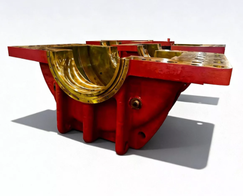
A shaft journal and its supporting bearing do not function independently. Their relationship depends on journal geometry, bearing condition, housing geometry, assembly datums, alignment, lubrication, and system loading. For that reason, shaft and bearing housing machining should be reviewed together whenever the drawing package or repair scope includes mating components. Such a review can expose tolerance-stack, datum, or fit issues that may be missed when each part is evaluated without system context.
The same principle applies when a white metal bearing supports a large rotating shaft. Journal diameter and surface condition must be compatible with the bearing design and specified clearance, while the housing has to locate the bearing correctly in the assembly. A supplier that can discuss both shaft features and bearing-related interfaces may provide more useful DFM feedback before machining begins. This coordination is particularly valuable for custom equipment and replacement parts where mating conditions may need to be confirmed from drawings or measurements.
A clear RFQ allows the manufacturer to evaluate the actual machining problem instead of quoting from a part name. The latest drawing should identify critical fits, geometric tolerances, machining features, and inspection requirements, while material condition and heat treatment should also be defined. Application information is useful when it explains which journals, couplings, sealing areas, or bearing interfaces are functionally critical. For replacement shafts, known wear or mating-component constraints should be disclosed rather than left for the supplier to infer.
For a useful quotation, include:
Current 2D drawings and, where available, a 3D model; material grade, certification, heat treatment, quantity, and delivery requirements.
Critical tolerances, datum references, runout or straightness requirements, surface finish, bearing and coupling interfaces, plus required NDT or inspection reports.
The operating application and known mating-component conditions, especially for marine shafting, turbine rotors, or replacement components.
This information helps determine whether turning, milling, drilling, grinding, special fixturing, or additional inspection stages are necessary. It also separates true precision shaft machining requirements from dimensions that are less functionally critical. Better technical input at the RFQ stage gives both buyer and manufacturer a clearer basis for the proposed production route.
Start with workpiece compatibility, then look beyond machine size. A capable supplier should be able to explain how the shaft will be supported, which operations establish datums, when critical dimensions will be checked, and how journals or sealing surfaces will be finished. Engineering communication matters because large shaft machining often requires manufacturability decisions before the blank reaches the machine. Quality documentation should also be matched to the project instead of relying on the same inspection sheet for every component.
For custom shaft machining, consider whether the supplier can coordinate forging, heat treatment, rough machining, finishing, grinding, and inspection where required. It is also useful to understand how drawing revisions and nonconformities are controlled. A technically credible supplier should identify limits, risks, and missing information before committing to production, particularly for large low-volume components where rework can be costly.
Large shaft machining commonly combines turning with milling, drilling, and grinding according to shaft geometry. Turning creates most cylindrical and stepped features, while milling or drilling produces keyways, flats, and bolt patterns. Grinding may be selected for critical journals or sealing surfaces requiring tighter size or surface-finish control.
Long shafts are more sensitive to deflection, support conditions, clamping, vibration, and the relationship between features located far apart. Difficulty rises when several bearing journals or coupling surfaces must share a controlled rotational axis. Planned support, staged machining, and intermediate checks help manage these risks.
The supplier should receive the latest drawing, material specification, heat-treatment requirements, quantity, critical tolerances, surface-finish requirements, and inspection expectations. Application details help clarify which interfaces are functionally important. Replacement projects should also include known mating-component or wear information where available.
Runout is evaluated by referencing and rotating the shaft in a controlled setup while measuring variation at specified surfaces with appropriate equipment. The exact method depends on shaft size, datum requirements, and the drawing. The inspection plan should define the measurement location and reference because “runout” can otherwise be interpreted too broadly.
Yes, drawing-based production is common for custom rotating components when the supplier has suitable machining and inspection capability. The drawing should define functional dimensions and interfaces clearly enough for production and verification. Where information is incomplete, a DFM review should resolve open questions before manufacturing.
Large shaft machining is best treated as an integrated engineering process rather than a single turning operation. Material condition, machining sequence, support, critical interfaces, grinding, and inspection all influence whether a heavy shaft will meet its drawing and assemble correctly with bearings, couplings, and adjacent components. For buyers, supplier evaluation should combine physical machine capacity with DFM support, process planning, staged quality control, and clear RFQ communication. TOTEM supports drawing-based manufacturing across shaft, marine propulsion, bearing, and other heavy rotating-equipment applications, allowing projects to be reviewed from both individual-part and system-interface perspectives.


