
Views: 0 Author: Site Editor Publish Time: 2026-08-26 Origin: Site
Compressor valves control the intake and discharge of gas in every compression cycle. They open and close hundreds or thousands of times per minute, driven by pressure differentials rather than external actuation. Because they operate at high frequency under extreme pressure and temperature, valves are among the most failure-prone components in a reciprocating compressor. A single failed valve can reduce compressor capacity, increase energy consumption, and allow gas contamination or backflow.
Recognizing valve failure symptoms early and understanding the root causes allows maintenance teams to act before a minor problem escalates. This guide covers the common symptoms of compressor valve failure, how to diagnose which valve is failing, what causes valve degradation, and the maintenance practices that extend valve life.
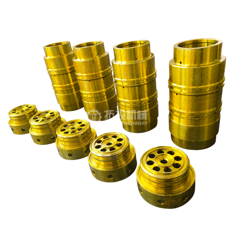
Capacity drop: The compressor delivers less gas at the same speed and suction pressure
Discharge temperature rise: Gas temperature at the discharge increases beyond normal range
Pressure irregularities: Suction or discharge pressure deviates from expected values, or pulsation patterns change
Valve cover temperature difference: One valve cover runs noticeably hotter or colder than others on the same cylinder
Unusual sound: Hissing, chattering, or metallic impact sounds from the valve area
Indicator card deviation: Pressure-volume diagram shows abnormal shape, indicating leakage or late opening
Any one of these symptoms does not always mean valve failure, but they are the primary indicators that should trigger valve inspection.
A reciprocating compressor uses two types of valves per cylinder: the inlet (suction) valve and the exhaust (discharge) valve. The compressor inlet valve opens during the return stroke when cylinder pressure drops below suction line pressure, allowing gas to enter. It closes when compression begins and cylinder pressure rises above suction pressure, preventing backflow into the intake line. The compressor exhaust valve opens at the end of the compression stroke when cylinder pressure exceeds discharge line pressure, releasing compressed gas. It closes when the piston reverses and cylinder pressure drops below discharge pressure, preventing backflow from the discharge line.
Both valves operate automatically, driven by pressure differentials, spring force, and valve plate elasticity. There is no cam or external actuation. This design is simple but demands that every component: the valve plate, spring, seat, and sealing surface, maintains precise geometry and material integrity through millions of cycles.
When a valve leaks, gas passes in the wrong direction during part of the cycle. A leaking inlet valve lets compressed gas flow back into the suction line during the compression stroke. A leaking exhaust valve lets discharge gas flow back into the cylinder during the return stroke. Both reduce the net amount of gas delivered per cycle. Capacity loss is often the first operational symptom, noticed when downstream pressure cannot be maintained or when flow meters show reduced delivery.
Leaking valves cause gas to be re-compressed. Gas that leaks back through the exhaust valve into the cylinder has already been compressed once and is hot. Re-compressing this hot gas raises the discharge temperature further. A rising discharge temperature, especially at one cylinder while others remain normal, is a strong indicator of valve leakage on that cylinder.
A leaking exhaust valve can allow hot discharge gas to flow back into the cylinder and then through the inlet valve into the suction line, raising suction temperature. If suction temperature rises above ambient plus expected approach temperature, investigate exhaust valve condition.
Compressor valves contribute to the pressure pulsation pattern in suction and discharge piping. A failing valve alters the pulsation signature. Changes in pulsation amplitude or frequency at a specific cylinder can indicate valve leakage or valve plate chatter. Pulsation monitoring systems can detect these changes online.
Measuring the temperature of individual valve covers provides a quick comparison method. A leaking exhaust valve often makes its cover run hotter because hot gas is leaking past it. A leaking inlet valve may make its cover run colder because compressed gas is leaking back through it into the suction line, expanding and cooling. A temperature difference of several degrees between valve covers on the same cylinder warrants inspection.
Valve plate chatter, a rapid tapping sound from the valve area, can indicate a valve plate that is not seating properly. A hissing sound may indicate gas leakage past a damaged valve plate or seat. A metallic impact sound may indicate a broken valve plate fragment moving inside the valve chamber. Any new sound from the valve area should be investigated immediately.
| Symptom | Likely Valve Problem | Diagnostic Method |
|---|---|---|
| Capacity drop at constant speed | Inlet or exhaust valve leakage | Indicator card analysis; valve cover temperature comparison |
| Discharge temperature rise at one cylinder | Exhaust valve leakage | Valve cover temperature; indicator card showing re-expansion line deviation |
| Suction temperature rise | Exhaust valve leaking back into cylinder | Suction temperature monitoring; indicator card analysis |
| One valve cover much hotter | Exhaust valve leakage on that valve | Thermocouple or IR thermometer on each valve cover |
| One valve cover much colder | Inlet valve leakage on that valve | Thermocouple or IR thermometer on each valve cover |
| Chattering sound from valve area | Valve plate not seating; possible spring failure or plate damage | Stethoscope or acoustic monitor; remove and inspect valve |
| Metallic impact sound | Broken valve plate fragment | Stop compressor immediately; inspect all valves on that cylinder |
The valve plate flexes with every cycle. Over time, the repeated bending stress causes fatigue cracking. The crack initiates at stress concentration points: notches, edges, or material defects. Plate fatigue is the most common failure mode for valves in continuous high-speed service. The fatigue life depends on plate material, thickness, lift distance, and the impact velocity at opening and closing.
Each time the valve plate opens and hits the lift stop, and each time it closes and hits the seat, it experiences impact. Excessive lift increases impact velocity, accelerating fatigue and potentially causing immediate fracture. Inadequate spring force allows the plate to flutter, increasing impact frequency. The design balance between lift, spring force, and flow area directly affects impact loading.
Corrosive gas components attack the valve plate and spring materials, reducing their strength and creating stress concentration points. Particulate matter in the gas erodes the sealing surfaces and plate edges. In dirty gas service, erosion can round the sealing edge of the seat, preventing the plate from sealing. Corrosion and erosion often work together: corrosion weakens the material and erosion removes the damaged surface, accelerating deterioration.
Liquid carryover into the cylinder can slam the valve plate open or closed with hydraulic force far exceeding the design load, causing immediate plate fracture. Deposits from dirty gas, oil coking, or polymerization can build up on the valve plate and seat, preventing proper seating. Liquid and deposit problems often cause sudden valve failure rather than gradual degradation.
Valve springs fatigue and break over time, particularly in high-frequency service. A broken spring changes the closing force on the plate, causing flutter, delayed closing, or incomplete seating. Multiple spring failures on the same valve can cause the plate to operate asymmetrically, leading to plate fracture.
Using a valve with the wrong lift, spring rate, or material for the actual operating conditions causes premature failure. Installing a valve with incorrect torque on the valve cap, damaged gaskets, or misaligned components can cause gas leakage past the valve body, distorting the temperature readings and leading to incorrect diagnosis. Over-torquing can distort the valve seat and prevent the plate from seating.
| Failure Cause | Mechanism | Prevention |
|---|---|---|
| Plate fatigue | Cyclic bending stress cracks the plate | Select plate material and thickness for actual speed and pressure; optimize lift to reduce impact; replace on schedule before fatigue life is reached |
| Impact damage | Excessive opening/closing velocity fractures plate | Verify lift setting matches operating conditions; maintain spring force; monitor for flutter |
| Corrosion | Gas chemistry attacks plate and spring material | Specify corrosion-resistant materials for gas composition; monitor gas quality; purge during shutdowns |
| Erosion from particles | Solid particles round sealing edges | Install and maintain gas filtration; monitor filter differential pressure; inspect valve seats for erosion |
| Liquid ingestion | Hydraulic force fractures plate or spring | Install liquid separation upstream; monitor for liquid carryover; train operators on startup and shutdown procedures |
| Deposit buildup | Oil coking or polymerization prevents seating | Maintain proper lubrication rate; inspect and clean valves at scheduled intervals; monitor gas composition |
| Spring failure | Spring fatigue or corrosion breaks spring | Replace springs at scheduled intervals; use corrosion-resistant spring material for the application |
| Improper installation | Incorrect torque, damaged gaskets, misalignment | Follow OEM torque sequence; inspect gaskets before installation; verify valve alignment |
Valves have a finite fatigue life. Waiting for failure costs more than scheduled replacement because a failed valve can damage other components and cause unplanned downtime. Establish replacement intervals based on operating hours, cycle count, and historical failure data for each compressor model. During scheduled valve replacement, inspect the seat, gasket, and valve chamber for wear and damage.
Clean gas is the single most important factor in valve longevity. Install coalescing filters and liquid separators upstream. Monitor filter differential pressure and replace filters before bypass. Install liquid level alarms in scrubbers. Sample gas periodically for corrosive components and particulate loading. Changes in gas composition may require valve material upgrades.
For lubricated cylinders, control the lubrication rate precisely. Excess lubricant causes deposit buildup on valve plates and seats. Insufficient lubricant increases ring and valve wear. Use the correct lubricant grade for the gas composition and operating temperature. For oil-free service, verify that valve materials are compatible with dry operation.
Install thermocouples or RTDs on each valve cover and trend the readings. A deviation of more than a few degrees between valve covers on the same cylinder is an early indicator of valve leakage. If the compressor has an indicator card system, compare current cards against baseline cards to detect changes in valve performance. Pulsation monitoring in the suction and discharge piping can detect valve leakage through changes in the pulsation signature.
When installing valves, follow the OEM torque sequence for valve caps. Use new gaskets every time. Inspect the valve seat in the cylinder for damage before installing the valve. Verify that the valve is the correct part for the cylinder position and operating conditions. Document the installation, including torque values, gasket condition, and any observations, to support future maintenance planning.
When sourcing reciprocating compressor parts including replacement valves, verify that the supplier provides material certificates, hardness testing, and dimensional inspection records. Valves manufactured with controlled plate material, proper heat treatment, and precision-machined sealing surfaces last longer and perform more consistently. Shanghai TOTEM Machinery Co., Ltd. manufactures and supplies compressor valves with ring, disc, and strip valve structures, with material selection and surface treatment matched to the operating media and conditions. Each valve undergoes quality control including key dimension inspection, hardness testing, and nondestructive testing as required. For valve specifications or replacement discussions, Contact Shanghai TOTEM Machinery for technical support.
Compressor valve failure is a leading cause of reciprocating compressor downtime, but it is also one of the most predictable. The symptoms of capacity loss, temperature deviation, pressure irregularities, and abnormal sound provide early warning. Systematic diagnosis using valve cover temperature comparison, indicator card analysis, and acoustic monitoring can identify which valve is failing before it fails completely. The root causes of plate fatigue, impact damage, corrosion, erosion, liquid ingestion, deposit buildup, and spring failure are all addressable through proper valve selection, gas quality management, lubrication control, online monitoring, and scheduled replacement. Investing in quality replacement valves and disciplined maintenance practices reduces unplanned downtime, extends compressor life, and lowers total cost of ownership.
Valve life varies widely with operating conditions. In clean gas service with proper maintenance, valves may last 8,000 to 20,000 hours. In dirty, corrosive, or high-speed service, life can be much shorter. The best approach is to track actual valve life for each compressor and establish replacement intervals based on your own data.
In some cases, minor seat damage can be repaired by lapping the sealing surface. Damaged valve plates, broken springs, and severely eroded seats require replacement of the valve assembly. Attempting to repair a fatigued valve plate is not recommended because the remaining material is already at reduced fatigue life.
Comparing valve cover temperatures on the same cylinder is the quickest method. A leaking exhaust valve typically runs hotter; a leaking inlet valve may run colder. An indicator card provides more detailed diagnosis by showing the specific deviation in the compression, discharge, or re-expansion lines.
Particulate matter in the gas erodes valve sealing surfaces and can lodge between the plate and seat, preventing proper closing. Liquid droplets can cause hydraulic impact that fractures valve plates. Installing and maintaining proper filtration and liquid separation upstream of the compressor is the most effective single measure for extending valve life.
Yes. If the gas composition changes to include more corrosive components such as hydrogen sulfide, chlorides, or moisture, the original valve plate and spring materials may not be suitable. Consult the valve supplier or compressor manufacturer to select materials rated for the new gas composition. Continuing to operate with inadequate materials leads to rapid valve failure.


