
Views: 0 Author: Site Editor Publish Time: 2026-07-23 Origin: Site
Catastrophic failure of a propeller shaft causes severe vessel downtime. Dry-docking expenses mount rapidly. Safety hazards put entire crews at risk. You must avoid these outcomes during the engineering phase. Shaft design is never a one-size-fits-all process. Engineers constantly balance torsional limits against harsh hydrodynamic forces. They must also calculate exact material fatigue thresholds.
We will provide a transparent, engineering-focused breakdown of these critical parameters. You will learn how to properly specify Marine Propulsion System Parts for commercial vessels. This guide bridges the gap between theoretical calculations and manufacturing reality. We aim to equip you with actionable technical insights. Expect a deep dive into precise sizing rules, material superiority, and advanced machining requirements.
Regulatory Baseline: Shaft diameters and material selections must strictly adhere to Classification Society rules (e.g., DNV, ABS, Lloyd’s Register).
Critical Speed Avoidance: Accurate calculation of torsional and whirling critical speeds is mandatory to prevent resonance-induced fatigue failure.
Material Superiority: A forged propulsion shaft offers significantly higher fatigue resistance and structural integrity compared to cast alternatives.
Precision Manufacturing: Partnering with facilities capable of high-tolerance custom OEM machining is essential to translate design parameters into a compliant, operational asset.
Slight deviations in design tolerances cause severe mechanical cascading effects. Accelerated bearing wear occurs almost immediately. Stern tube seal leaks follow shortly after. Ultimate fatigue failure becomes inevitable. These errors compromise the entire vessel structure. They lead to catastrophic propulsion loss at sea. You cannot afford to underestimate these initial engineering parameters.
The shaft does not operate alone. You must integrate it flawlessly into a larger mechanical ecosystem. Design parameters account for dynamic engine power delivery. Gearbox output dictates rotational forces transferred down the driveline. Specific propeller configurations matter heavily. Pitch, skew, and rake drastically alter load distributions. Engineers evaluate these interconnected variables simultaneously. They ensure harmonic balance across the entire drivetrain.
Evaluate total lifecycle reliability when procuring components. Monitor expected maintenance intervals closely. Ensure strict regulatory compliance at every phase. We look beyond just the initial purchase price. Successful procurement guarantees decades of uninterrupted service. It aligns theoretical engineering limits with harsh oceanic realities.
Engineers use empirical formulas first. Classification Societies like DNV and ABS provide these strict rules. They base baseline calculations on shaft horsepower and rotational RPM. This creates a highly reliable foundation. Next, design teams apply Finite Element Analysis (FEA). FEA reveals hidden localized stress concentrations. You can then refine the final geometry. This dual approach ensures maximum structural safety.
You must differentiate the design rules for specific driveline sections. A Propeller Shaft faces direct seawater exposure. It supports massive cantilevered propeller weights. It handles direct thrust forces and extreme bending moments. Conversely, an Intermediate Shaft primarily transmits pure torque. It stays securely protected inside the vessel hull.
Shaft Application Differences
| Parameter | Tail/Propeller Axis | Intermediate Axis |
|---|---|---|
| Primary Load | Combined bending and torsional forces | Predominantly torsional forces |
| Environment | Direct seawater immersion | Inboard, protected dry hull |
| Diameter Sizing | Requires larger diameter for bending resistance | Can be optimized for smaller diameter |
| Key Vulnerability | Corrosion fatigue and seal wear | Torsional vibration resonance |
Calculate torsional stress accurately. Identify the maximum allowable continuous torsional stress. Account for sudden transient torsional spikes. Heavy weather causes these rapid load fluctuations. You must also factor in extreme bending moments. The overhanging weight of the propeller creates severe bending forces. Dynamic hydrodynamic loads compound this stress. Turning operations shift forces dynamically across the bearings. Your design must absorb these multi-directional loads safely.
Define critical speed carefully during early engineering. Whirling and torsional critical speeds cause severe resonance. Resonance destroys mechanical components quickly. It shatters bearing housings and fractures steel. You must avoid continuous operation within restricted speed ranges. Engineers officially call these "barred speed ranges". Vessels must pass through them rapidly. Design parameters strictly dictate the width of these restricted bands.
Simulate cyclic loading thoroughly. Computational models predict exact fatigue life optimization. They forecast component performance over a 20 to 30 year lifespan. This ensures long-term operational integrity. Engineers run thousands of virtual load cycles. They identify exactly where micro-fractures might initiate over decades.
Use design modifications for physical stress relief. Mitigate dangerous stress concentration factors effectively. Small geometric changes yield massive fatigue life improvements. Implement the following physical design strategies:
Increase fillet radii aggressively at all distinct section transitions.
Eliminate sharp internal corners in keyway slots.
Apply specialized surface hardening techniques to bearing journals.
Optimize taper profiles to distribute propeller hub clamping forces evenly.
Relieve residual internal stress through post-machining thermal treatments.
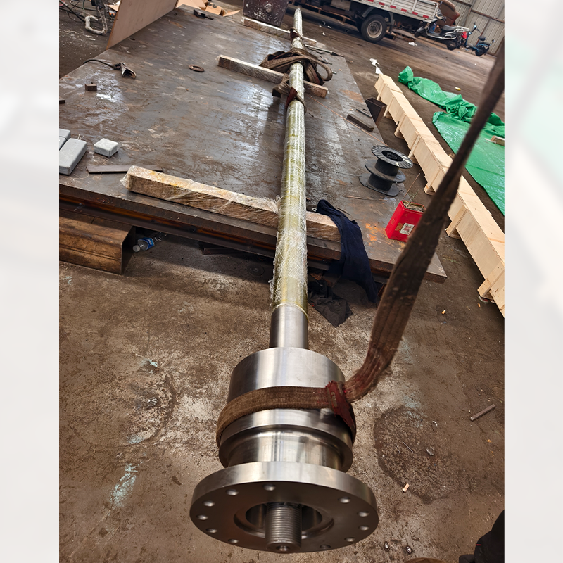
Forging heavily outperforms casting and rolling techniques. A Forged Propulsion Shaft represents the absolute industry standard. Commercial vessels and high-performance craft rely entirely on them. The forging process ensures continuous internal grain flow. It eliminates dangerous internal voids. This manufacturing method maximizes overall structural integrity. Cast alternatives often hide microscopic porosity defects. Those defects invite sudden catastrophic failure under heavy torsional loads.
Evaluate raw material grades carefully. Carbon manganese steel offers excellent baseline reliability. High-alloy steels provide elevated strength thresholds. Duplex stainless steels deliver extreme durability. You must strictly balance yield strength against ultimate tensile strength. Notch toughness remains equally vital. It prevents initial micro-cracks from propagating into full fractures.
Common Material Grades and Properties
| Material Grade Type | Typical Yield Strength | Primary Advantage | Ideal Application Scenarios |
|---|---|---|---|
| Carbon Manganese Steel | ~300 - 400 MPa | Cost-effective baseline strength | Standard commercial bulk carriers |
| Low-Alloy Forged Steel | ~450 - 600 MPa | High tensile capacity | Ice-class vessels, tugboats |
| Duplex Stainless Steel | ~500 - 700 MPa | Superior corrosion immunity | High-speed craft, naval vessels |
Address harsh marine operating environments actively. Cyclic stress and saltwater corrosivity combine destructively. This specific combination accelerates premature fatigue failure. Unprotected steel deteriorates rapidly in oxygen-rich seawater.
Incorporate robust protective measures. Use shrunk-fit bronze or heavy stainless steel liners. Apply specialized marine-grade epoxy coatings. Mandate strict cathodic protection requirements into your base parameters. Sacrificial anodes or impressed current systems prevent galvanic corrosion. You must design the shaft assembly to accommodate these protective layers seamlessly.
Strict machining tolerances dictate long-term success. You need advanced multi-axis CNC capabilities. Custom OEM Machining achieves exact dimensional accuracy. It guarantees highly specific surface finishes. Specific Ra values ensure stern tube seal integrity. Rough surfaces destroy polymer seals rapidly. Perfect machining prevents catastrophic oil leaks into the ocean.
Enforce Quality Assurance and Non-Destructive Testing (NDT). Ultrasonic Testing (UT) finds hidden deep flaws. Magnetic Particle Inspection (MPI) detects invisible surface cracks. These strict protocols are entirely mandatory. Apply them before, during, and after the machining process. They guarantee absolutely zero subsurface defects. A trustworthy manufacturing facility handles these tests in-house.
Demand official Classification Society Certification. Your manufacturing partner needs globally recognized facility approvals. They must provide formal Type Approval Certificates (TAC). Require certified 3.2 material documents for every single forged billet. These documents trace the steel back to the original melting furnace. They prove the chemical composition meets structural requirements exactly.
Look for extensive engineering support. A capable OEM partner provides empirical feedback. They excel at Design for Manufacturability (DFM). Their specific machining insights refine your initial design parameters. They help you avoid overly complex geometries. This collaboration reduces manufacturing time while improving final part reliability.
Robust propeller design requires a rigorous synthesis of classification rules. We rely heavily on advanced fatigue modeling. Uncompromising material standards ensure vessel safety. You cannot separate theoretical calculations from practical machining limitations.
Keep these concise next steps in mind:
Engage manufacturing engineering teams early in the design phase.
Align theoretical parameters directly with precision machining capabilities.
Calculate barred speed ranges to mitigate severe torsional resonance.
Demand fully traceable 3.2 material certificates for every component.
Prioritize forged materials over cast alternatives to guarantee internal grain integrity.
A: The minimum diameter depends on the maximum continuous rating (MCR) of the engine. Shaft RPM and material tensile strength play critical roles. Engineers also apply specific Classification Society safety factors. Bending moments from the propeller weight further influence the final required diameter.
A: Intermediate shafts are generally installed inboard. The hull protects them from corrosive seawater. They primarily handle pure torsional loads. This allows for a slightly smaller diameter compared to the tail shaft. The tail shaft must endure combined bending and torsional loads.
A: Standard off-the-shelf parts cannot accommodate bespoke engine-gearbox-hull dynamics. Commercial vessels require highly specific alignments. Custom machining ensures perfect geometrical tapering. It provides exact Ra surface finishes for tight seal fits. This precision prevents devastating oil leaks and catastrophic mechanical failure.
A: It is a specific RPM band. The shaft experiences severe torsional resonance within this band. Engineers call this critical speed. Design parameters dictate this exact range. Operators must pass through it quickly. They must never use it for continuous operation.


