
Views: 0 Author: Site Editor Publish Time: 2026-06-29 Origin: Site
The intermediate shaft stands as the critical bridge between the propulsion shaft and the propeller shaft in a marine shafting line. When components spin at high velocities under immense torque, this connection bears the brunt of the mechanical forces. Failure or misalignment here can result in serious drivetrain damage. Such failures may force emergency dry-docking and disrupt entire fleet schedules.
Engineering teams face a continuous challenge when evaluating, specifying, and sourcing high-reliability marine propulsion system parts. You must navigate stringent classification society standards from IACS members. Simultaneously, you must balance extended procurement lead times. A single material flaw or machining error can derail a complex shipbuilding or retrofit project.
We will provide a comprehensive, decision-stage framework to help you navigate these demanding requirements. You will learn how to properly specify intermediate shafts, evaluate distinct material choices, and confidently select capable manufacturing partners. Our guide breaks down the engineering rationale behind these vital drivetrain choices.
Material integrity dictates lifespan: A forged intermediate shaft offers superior fatigue resistance and grain structure alignment compared to alternative manufacturing methods.
Alignment and integration are non-negotiable: Precise machining of the marine gearbox shaft connections and bearing journals is required to prevent torsional vibration and premature bearing failure.
Customization meets compliance: Specifying a custom marine shaft requires strict adherence to classification society requirements (e.g., ABS, DNV, Lloyd’s Register) regarding ultrasonic testing and material certification.
Vendor evaluation requires technical diligence: Shortlisting suppliers should rely on their in-house non-destructive testing (NDT) capabilities, forging capacity, and track record with specific vessel types.
The mechanical burden placed on a vessel's shafting arrangement is immense. A prime mover generates massive rotational force. The intermediate shaft must transmit this maximum torque directly to the propeller. However, a ship hull is never entirely rigid. Ocean waves cause constant dynamic bending. We refer to this movement as hogging and sagging. The shaft must transmit power while simultaneously absorbing these dynamic hull deflections and transient peak loads.
Engineering teams measure the operational success of this component through strict performance criteria. You cannot compromise on these benchmarks without risking the entire vessel's safety.
Zero disruption in torque transmission: The component must handle continuous reversing loads during maneuvers like crash astern without yielding.
Minimal vibration transmission to the hull structure: Excessive vibration damages line bearings and compromises crew comfort.
Compliance with the vessel's specific torsional vibration analysis (TVA): The mass-elastic properties must match the system to prevent destructive resonance.
Understanding exact system placement is vital for proper specification. Engineers position this component between the propulsion shaft and the propeller shaft. At the forward end, it couples with the propulsion shaft; at the aft end, it connects with the propeller shaft, also called the tail shaft in many marine shafting layouts. Along its length, specialized line bearings support its weight. This central positioning makes it the backbone of the drivetrain.
A common mistake during retrofits involves ignoring the changing stiffness of modern hulls. When you upgrade an engine, the new torque profile changes how the shaft behaves. You must re-evaluate the entire line bearing distribution to ensure the shaft remains properly supported under the new dynamic loads.
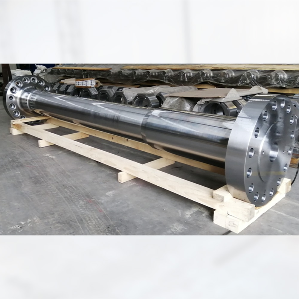
When selecting materials for large-scale maritime applications, engineers primarily compare different steel fabrication methods. While casting offers cost advantages for complex shapes, it introduces severe structural vulnerabilities. Modern maritime classification societies heavily favor forging for critical drivetrain components.
Forging remains the definitive industry standard for two main structural reasons. First, the process optimizes grain flow. Heavy hydraulic presses deform the hot steel. This process aligns the internal metal grain precisely with the physical shape of the shaft. This alignment maximizes structural integrity under continuous rotational stress. Second, forging drastically reduces internal porosity. It eliminates the internal voids and gas pockets common in cast steel alternatives.
Specifying a forged intermediate shaft requires evaluating different steel grades based on your specific engine output and vessel application. You must balance required tensile strength against material toughness.
| Material Grade | Type | Typical Tensile Strength (MPa) | Best Application Scenario |
|---|---|---|---|
| C45 / S45C | Carbon Steel | 580 - 700 | Standard commercial vessels, bulk carriers, low-stress environments. |
| 34CrNiMo6 | Alloy Steel | 900 - 1100 | High-speed ferries, naval vessels, high-torque applications requiring fatigue resistance. |
| 42CrMo4 | Alloy Steel | 850 - 1000 | Ice-class vessels needing superior impact toughness at low temperatures. |
Quality assurance represents the foundation of trustworthiness in maritime procurement. You must demand full traceability from your manufacturing partner. This transparency starts with the raw material melt origin. It extends to comprehensive heat treatment records showing exact quenching and tempering curves. Finally, third-party metallurgical analysis must verify the final mechanical properties. Without these documents, a classification society surveyor will reject the component.
Procurement teams frequently debate whether off-the-shelf dimensions suffice or if bespoke engineering is required. You must base this decision on several key evaluation dimensions, including integration limits, classification rules, and vessel operational profiles.
Certain scenarios strictly dictate customization requirements. Vessel retrofits present the most common challenge. Older gearbox outputs rarely match the flange dimensions of modern tail shafts. A custom propulsion connection shaft bridges this dimensional gap seamlessly. High-performance or ice-class vessels also demand specialized engineering. These ships require enhanced flange thicknesses and broader transition radii. These specific geometric changes mitigate dangerous stress concentrations during heavy ice impacts.
When you commission a custom marine shaft, you must rigorously verify several design specifications during the drafting phase. A single dimensional error here ruins the installation process.
Coupling flange dimensions: Evaluate whether integral forged flanges provide better rigidity than hydraulically fitted couplings for your specific torque profile.
Main journal bearing locations: Ensure the surface finish tolerances meet strict Ra values (typically Ra 0.8 or better). This precise finish maintains the hydrodynamic oil film required to prevent bearing wipe.
Bolt hole configurations: Specify reamed holes for hydraulically fitted bolts. If you allow excessive clearance in the bolt holes, the fasteners will shear under reversing loads.
Below is a quick reference chart summarizing the decision matrix for standard versus custom sourcing.
| Decision Factor | Standard Design | Custom Design |
|---|---|---|
| Vessel Age | New builds with matched OEM components. | Mid-life retrofits and repowering projects. |
| Operating Environment | Open water, temperate climates. | Ice-class regions, heavy sea states. |
| Lead Time Sensitivity | Shorter procurement window. | Longer lead time acceptable for precision fit. |
| Classification Rule Changes | Vessel grandfathered into old rules. | Vessel must upgrade to new IACS strength rules. |
Procuring a high-quality component solves only half the problem. Even the finest steel will fail catastrophically if installation protocols are ignored. Implementation considerations dictate that shipyard engineers must handle the shaft with extreme precision.
Shaft alignment dynamics represent a major implementation risk. Improper load distribution across line bearings causes excessive localized friction. This friction inevitably leads to bearing wipe and shaft scoring. Engineers must choose between straight-line alignment and rational alignment. Straight-line alignment works adequately for small, stiff-hulled boats. However, large commercial vessels require rational alignment. This advanced technique pre-calculates bearing offsets to account for how the hull bends dynamically under different cargo loads.
Torsional and axial vibration present another hidden danger. A prime mover fires in distinct pulses. The propeller blades encounter uneven wake fields. These forces twist and compress the driveline. If mismatches exist in the mass-elastic properties between the intermediate shaft, the marine gearbox shaft, and the prime mover, resonance occurs. This resonance leads to severe gear hammering or rapid shaft fatigue.
You must enforce strict mitigation strategies during the installation phase to prevent these vibration failures. Follow these mandatory procedures:
Perform comprehensive gap and sag calculations before mating the flanges. This verifies the preliminary alignment is correct.
Utilize advanced optical or laser alignment tools during the final installation to ensure tolerances remain within hundredths of a millimeter.
Conduct hydraulic jack-up tests to physically measure the actual load resting on each line bearing.
Mandate continuous sea-trial vibration monitoring across the entire RPM range to validate the torsional vibration analysis (TVA).
Filtering unqualified suppliers requires a rigid vendor evaluation framework. When dealing with critical maritime infrastructure, you cannot afford to rely on unverified claims. You must systematically evaluate a facility's technical capacity and historical track record.
You must demand several essential capabilities before adding a vendor to your approved shortlist. First, verify their classification society approvals. IACS member certifications (such as ABS, BV, DNV, LR, or NK) must accompany the finished product. Specifically, demand a 3.2 material certificate. A 3.1 certificate only involves internal testing. A 3.2 certificate proves an independent class surveyor witnessed the testing.
Second, evaluate their in-house testing facilities. Mandatory inspections include visual, dimensional, ultrasonic (UT), and magnetic particle (MT) testing. If a facility outsources their NDT, it adds weeks to your lead time and complicates accountability. Third, assess their machining tolerances. The vendor must demonstrate the capability to achieve extremely tight dimensional tolerances for coupling fits and bearing journals on multi-meter lengths of heavy steel.
Once you identify a qualified vendor, execute your next-step actions promptly. Request a detailed technical consultation. Submit your vessel's structural drawings and TVA reports for a manufacturability review. Finally, confirm their forging lead times and material availability well before finalizing your dry-dock scheduling. Raw material shortages can easily disrupt a planned installation.
The intermediate shaft remains the most critical link in a vessel's propulsion chain. Any compromises in material integrity or machining precision directly impact fleet availability and vessel safety. A robust drivetrain ensures smooth power delivery and protects expensive gearbox components from dynamic hull stress.
To succeed in your procurement strategy, prioritize forged materials over cast alternatives. Enforce rigorous IACS compliance by demanding verified 3.2 material certificates. Furthermore, ensure exact dimensional integration with your existing propulsion shaft and propeller shaft parameters through precise custom engineering.
We invite marine engineers and procurement officers to take the next step. Share your technical drawings, operational profiles, or TVA reports with your chosen engineering team. Request a comprehensive feasibility assessment and a detailed project quote to ensure your next dry-docking proceeds flawlessly.
A: The propeller shaft, also known as the tail shaft in many marine shafting systems, extends toward the stern and connects directly to the propeller. In contrast, the intermediate shaft remains inboard and acts as the connecting shaft between the propulsion shaft and the propeller shaft. This position allows torque to transfer smoothly through the shafting line while maintaining proper alignment and bearing support.
A: Standard IACS members (like ABS, DNV, or Lloyd's Register) enforce strict rules. The chosen class society must pre-approve the steel grade and the specific forging process. Furthermore, a class surveyor must physically witness the final non-destructive testing (NDT) to issue a valid 3.2 material certificate.
A: Engineers typically connect the intermediate shaft to adjacent propulsion shaft and propeller shaft sections using integral forged flanges. They secure these flanges tightly with hydraulically fitted bolts in reamed holes. For highly stressed applications or tight retrofit spaces, engineers may alternatively use hydraulic shrink-fit couplings to ensure stable torque transfer.
A: Realistic timelines generally range from 12 to 24 weeks. This duration depends heavily on raw steel block availability, the facility's heavy forging schedule, machining complexity, and mandatory inspection hold points required by the classification society surveyor.


