
Views: 0 Author: Site Editor Publish Time: 2026-07-17 Origin: Site
In marine engineering, millimeter-level discrepancies in shaft machining escalate rapidly. Once a vessel gets underway, these tiny errors cascade into severe hydrodynamic and mechanical failures. Static machining precision at the manufacturing facility dictates dynamic alignment stability in the water. A perfectly machined shaft creates a highly reliable baseline. Conversely, an imperfect one guarantees misalignment. This happens regardless of shipyard installation skill. Assessing a machining partner’s exact tolerance capabilities remains a critical risk-management decision. Fleet operators and shipyards must prioritize precise manufacturing to ensure safe operations. Through strict quality control, they prevent catastrophic failures far from shore. Read on to discover how dimensional accuracy directly drives propulsion reliability. You will learn to navigate the operational risks of substandard parts. We also explore why dynamic forces demand near-perfect static machining benchmarks.
Minor dimensional deviations in machining (runout, concentricity) multiply exponentially along the shaftline, directly impacting final alignment.
Precision machining prevents premature wear on critical components, drastically reducing the risk of catastrophic bearing failure and unplanned drydocking.
Evaluating a supplier’s Custom OEM Machining capabilities requires analyzing their class-society compliance (e.g., ABS, DNV) and inspection methodologies.
Static alignment accuracy is only a baseline; true machining precision accounts for the dynamic, fluctuating forces experienced at sea.
Shaftline misalignment represents more than a mere technical error. We frame it as a primary driver of unplanned maintenance and severe vessel downtime. Fuel inefficiency directly follows any compromise in the propulsion driveline. Using poorly manufactured Marine Propulsion System Parts sets you up for failure long before the ship leaves drydock. Substandard machining embeds geometric flaws deep into the system. These invisible flaws severely degrade performance over the vessel's lifespan.
Poor alignment unevenly distributes massive rotational loads across the shaftline. This uneven distribution drastically accelerates wear on stern tube seals. It also severely damages the Journal Sliding Bearing. When loads localize on edge points, the hydrodynamic oil film collapses. Metal-on-metal contact then ensues. Such friction creates localized hot spots, leading to rapid component degradation.
Micro-misalignments cause severe lateral and torsional vibrations throughout the hull. Over time, these relentless vibrations induce metal fatigue. Fatigue cracks propagate silently through the steel structure. Eventually, this process leads to potential shaft fractures underway. Catastrophic failures like these strand vessels and incur massive salvage costs.
You must clearly define a successful procurement outcome for these critical parts. Success means predictable lifecycle maintenance and strict class compliance. It also guarantees extended operational intervals between mandatory drydockings. Reliable machining essentially buys you operational peace of mind.
Best Practice: Always require documented runout tests before accepting delivery of heavy propulsion parts.
Common Mistake: Relying solely on installation teams to correct factory-level machining deviations.
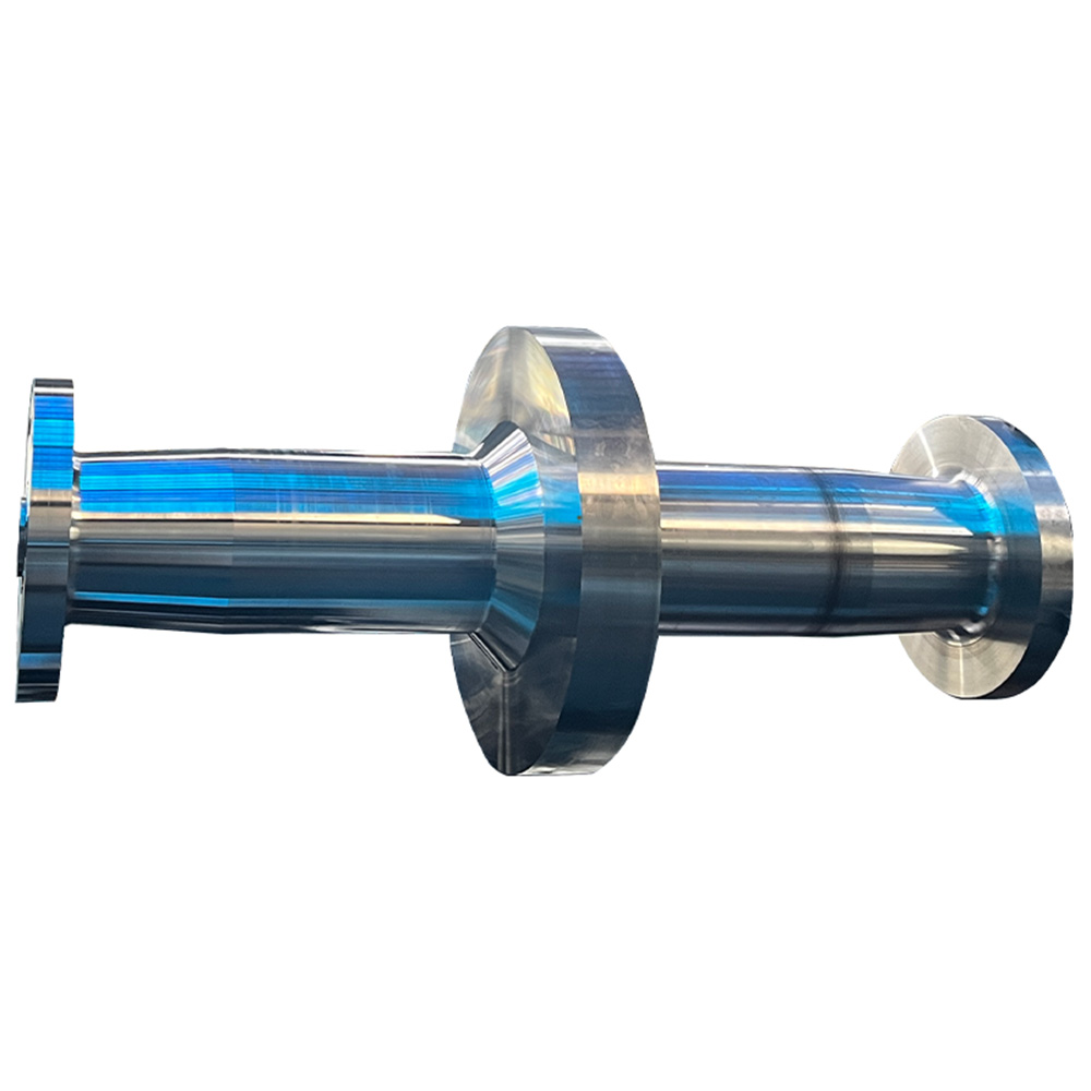
Specific machining metrics directly influence the straightness of the entire propulsion line. Technical expertise requires breaking down these exact dimensional tolerances. Runout, concentricity, and surface finish govern mechanical behavior. Even slight deviations alter the stress distribution across the entire shaftline. Engineers meticulously calculate these tolerances to ensure perfect rotational symmetry.
Errors at the coupling flanges create massive downstream problems. Imagine joining a Propeller Shaft to an Intermediate Shaft using poorly machined faces. Lack of flange parallelism induces severe angular misalignments. Lack of concentricity creates distinct offset misalignments. Installers find these specific geometric errors impossible to correct during hull assembly. The steel simply refuses to align naturally.
The machining of the propeller boss taper dictates exact seating. Precision taper angles ensure the propeller grips the shaft evenly. Surface finish directly influences this hydrodynamic balance. Rough surfaces invite fretting corrosion under heavy cyclic loading. This corrosion eventually compromises the structural integrity of the propeller hub connection.
The multiplier effect makes small errors incredibly dangerous. A fraction-of-a-millimeter machining error at one end creates disaster. We outline the cascading stages of this effect below:
A microscopic angle error exists at the forward flange face.
The bolted coupling forces the connected shaft slightly off-center.
This deviation multiplies over the ten-meter span of the connected component.
The tail-end swings through a massive, unacceptable runout arc.
The resulting vibration shreds adjacent stern tube bearings.
Ships are inherently flexible, non-rigid structures. They bend and twist continuously while operating at sea. Hull deflections change based on varying cargo loads and ballast conditions. Furthermore, fluctuating propeller hydrodynamic forces alter the alignment dynamically. Heavy seas generate immense transient loads across the stern. Therefore, static alignment on blocks never represents true operational conditions.
Highly accurate baseline machining provides a critical safety margin. This margin absorbs unavoidable dynamic forces safely. Poor static alignment already pushes mechanical tolerances to their absolute limits. Consequently, dynamic loads easily push the stressed system into catastrophic failure. Precision machining gives the shaft room to flex without breaking the oil film.
Strict design compliance remains absolutely necessary for maritime safety. You must align machined products with stringent class society guidelines. The ABS Guidance Notes on Propulsion Shafting Alignment provide excellent frameworks. DNV and Lloyd's Register offer similarly rigorous standards. Meeting these standards ensures the components survive violent dynamic shifts.
| Operational Condition | Force Type | Impact on Shaft Alignment | Required Machining Margin |
|---|---|---|---|
| Drydock (Static) | Gravity | Natural sag between supports | Zero deviation from baseline |
| Cargo Loading | Hull Bending | Bearing elevation changes | High bearing clearance tolerance |
| Heavy Seas | Hydrodynamic | Lateral and vertical thrust | Flange parallelism perfection |
| Full Ahead Speed | Torsional | Twisting and compression | Perfect boss taper seating |
Standard aftermarket replacements rarely meet the demands of modern mega-vessels. Custom OEM Machining backed by specific engineering data offers far superior reliability. Custom manufacturing strictly adheres to original blueprint tolerances. Standard aftermarket parts often utilize looser, generalized tolerance bands. You must choose solutions engineered specifically for your exact vessel class.
You need to scrutinize a supplier's internal quality control processes carefully. Look for in-house laser metrology and advanced coordinate measuring machines (CMM). Top-tier facilities conduct extensive runout testing on specialized heavy-duty lathes. They never rely on simple hand-tool measurements for massive propulsion components. Advanced metrology removes human error from the quality control equation.
Material traceability ensures the underlying steel possesses adequate strength. Emphasize the importance of full material test reports (MTRs). You also need verifiable manufacturing compliance with IACS members. Without proper metallurgical documentation, perfectly machined geometry means nothing. Inferior steel deforms rapidly under standard operational loads.
Buyers should actively request historical case studies from potential suppliers. Demand comprehensive tolerance capability reports covering similar projects. Never accept marketing claims at face value without empirical evidence. A reputable machining partner happily provides anonymized inspection data from past deliveries.
Best Practice: Audit the supplier's CMM calibration logs before signing the contract.
Common Mistake: Accepting final parts without reviewing the raw dimensional inspection reports.
A dangerous handover gap exists between the facility and the shipyard. Transporting heavy shafts introduces severe bending risks if improperly supported. Even perfect lathe machining degrades if the shaft warps during transit. The installation team often wrongly blames the manufacturer for transport-induced bends. Clear communication and rigid lifting protocols prevent this expensive confusion.
Traditional alignment methods utilize simple optical tools and dial indicators. Modern shipyards prefer highly advanced laser alignment technologies. However, you must understand a fundamental truth regarding these tools. Even the most advanced laser alignment cannot fix a physically warped shaft. Lasers position the components perfectly, but they cannot erase manufactured geometrical defects.
Implement strict mitigation strategies to protect your project timeline. Recommend mandatory pre-installation runout checks upon arrival at the shipyard. Conduct rigorous factory acceptance tests (FAT) before the shaft ships out. Discovering a machining error in the drydock causes catastrophic financial delays. Finding it on the factory floor allows for immediate, cost-effective correction.
A proactive approach unites the machining facility and the installation crew. It ensures everyone works from the same verified dimensional baseline. Ultimately, this synergy guarantees a smooth, vibration-free propulsion system launch.
Shaft alignment begins fundamentally on the lathe, not inside the hull. No amount of shipyard expertise overcomes inherently flawed manufacturing geometries. Precision tolerances protect your heavy equipment from premature wear and catastrophic failure. They provide the necessary margins to handle violent dynamic forces at sea. When you control dimensions meticulously, you ensure reliable, long-term hydrodynamic performance.
Decision-makers must prioritize suppliers capable of proving strict dimensional control. Evaluate their metrology equipment, material traceability, and dynamic load understanding carefully. Thorough vetting prevents costly unplanned drydockings down the line. We encourage you to review your current supplier’s quality control documentation immediately. Request a technical consultation before beginning your next propulsion system retrofit or new build.
A: Runout creates a severely eccentric load path during shaft rotation. This uneven motion breaks the protective hydrodynamic oil film inside the bearing. Consequently, boundary lubrication fails, leading to direct metal-on-metal contact. This friction causes rapid overheating, accelerated wear, and sudden bearing failure.
A: Acceptable tolerances depend heavily on shaft diameter, maximum RPM, and specific class society rules. Standard guidelines from ABS or DNV typically dictate extremely tight margins. They usually require flange concentricity and total indicator runout measured in hundredths of a millimeter.
A: No. Laser alignment simply ensures components sit correctly relative to one another inside the hull. It cannot correct inherent geometrical defects manufactured directly into the steel. A non-parallel flange remains crooked, regardless of how perfectly you aim a laser through it.
A: Custom OEM machining guarantees adherence to exact original material specifications. It strictly follows necessary stress-relief processes and precise dimensional tolerances. This specialized approach honors the vessel's original engineering calculations, dramatically reducing overall operational risk at sea.


