


Why Marine Propeller Shafts Fail Under Combined Conditions
Most serious shaft failures cannot be explained by nominal torque alone. A rotating propulsion shaft is subjected to repeated loading cycles, while bending, torsion, vibration, surface condition, local geometry, and environmental exposure influence how those loads are distributed. Over time, a small surface or subsurface discontinuity can become a fatigue initiation point and progressively grow until the remaining section can no longer carry the operating load.
Propeller shaft fatigue failure often begins at a local discontinuity rather than in a uniform section of the shaft. Keyways, shoulders, fillets, coupling interfaces, journal transitions, machining marks, scratches, fretted surfaces, corrosion pits, and previously repaired areas deserve greater inspection attention because they can increase local stress.
This means a shaft can have adequate base material and still experience failure if its geometry, surface condition, fit, or actual operating environment produces severe stress concentration. The condition of a small transition radius or a damaged fitted surface may therefore be more important than its appearance initially suggests.
A Marine propeller shaft also operates as part of a connected propulsion system rather than as an isolated rotating component. Its relationship with couplings, bearings, sealing arrangements, and adjacent shaft sections affects alignment and load distribution. The shaft body, coupling areas, journals, and transition sections should consequently be assessed together instead of treating a crack or worn surface as an independent defect.
Corrosion adds another layer of risk. General surface oxidation may not immediately reduce the shaft section enough to cause failure, but localized pitting can create small notches where cyclic stresses concentrate. If a fatigue crack begins at the bottom of a corrosion pit, continued loading and environmental exposure can accelerate deterioration. Shaft corrosion fatigue should therefore be evaluated through both material loss and crack-initiation potential rather than appearance alone.
Warning Signs That Should Change Inspection Priority
A visible crack is an obvious warning, but it may already represent a relatively advanced stage of damage. Earlier indications are often changes in the way the shafting system behaves. One symptom alone does not prove that the propeller shaft is defective, but a developing trend, several symptoms appearing together, or an abnormality following grounding, propeller impact, bearing work, coupling work, or shaft alignment changes should increase inspection priority.
Vibration is particularly important because it may result from unbalance, misalignment, bearing deterioration, shaft deformation, propeller damage, looseness, or an evolving crack. Its diagnostic value comes from comparison rather than from one isolated reading. Operating speed, load, vibration direction, frequency characteristics, and deviation from the vessel's previous baseline should be considered together.
Bearing temperature, lubrication condition, and journal behavior provide another view of shaft condition. A change in bearing load distribution can indicate altered shaft alignment or deflection. Conversely, bearing deterioration can change the way the shaft is supported and increase bending stress elsewhere. A hot bearing should not automatically be treated as only a bearing problem, just as abnormal shaft vibration should not automatically be treated as only a shaft problem.
| Observation | Inspection Priority | First Areas to Check |
|---|---|---|
| New or increasing vibration | High | Alignment, bearings, coupling areas, shaft runout, propeller condition |
| Repeated bearing overheating | High | Bearing surface, lubrication, load distribution, journal condition, alignment |
| Corrosion pits or protective-layer damage | High at stressed locations | Water-exposed areas, transitions, journals, seal-adjacent surfaces |
| Fretting or metallic debris | High | Couplings, fitted surfaces, keyways, bearing interfaces |
| Oil leakage or abnormal seal behavior | Medium to high | Seal condition, shaft surface, eccentric running, alignment |
| Scratches, dents, or repair marks | Depends on location and depth | Stress-concentrated areas and surfaces under cyclic bending |
| Unexplained propulsion noise | Medium to high | Bearings, coupling fit, shaft alignment, propeller, support structure |
The important point is prioritization. A shallow surface mark in a relatively low-stress area and a similar mark beside a keyway or diameter transition should not automatically receive the same risk rating. Location, orientation, depth, operating history, and the surrounding stress field need to be considered together.
A Practical Propeller Shaft Crack Inspection Workflow
An effective inspection process should move from system behavior to local defect confirmation. Starting immediately with one nondestructive examination method can identify some defects, but it may not reveal why they developed. If the initiating condition remains unchanged, the same failure mechanism can return even after the damaged area has been repaired.
1. Review Operating History Before Opening the Shaft Line
Compare recent vibration behavior, bearing temperatures, lubrication observations, impacts, overload events, docking work, shaft repairs, propeller work, and alignment changes. The objective is to identify what changed before the abnormal symptom appeared.
For example, vibration that begins after a propeller impact should lead to a different inspection emphasis than vibration that has gradually increased over a long operating period. Establishing this sequence helps inspection teams prioritize likely initiating conditions instead of examining every possible cause with equal weight.
2. Inspect the Complete Shafting Path
Examine accessible shaft surfaces, couplings, fasteners, journals, bearings, seals, and support structures. Particular attention should be given to corrosion pits, fretting, unusual polished areas, scoring, dents, machining marks, abnormal contact patterns, and evidence of relative movement between fitted parts.
Examining the complete shafting path also helps distinguish between a root cause and a secondary effect. Journal wear, for example, may be the result of poor alignment, while an already deteriorated bearing may itself contribute to abnormal shaft loading.
3. Check Geometry and Alignment
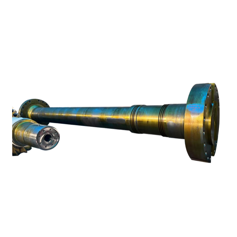
Runout, straightness, coupling condition, bearing positions, and shaft-line alignment should be evaluated where appropriate. A Forged intermediate shaft connects major sections of the propulsion shafting and works together with bearings and adjoining shaft segments. Its geometric condition can therefore influence vibration, support, and alignment throughout the shaft line.
Replacing a damaged propeller shaft without confirming the geometry of the intermediate shaft, bearing supports, and coupling interfaces can leave the replacement shaft exposed to the same abnormal bending or alignment conditions that contributed to the original problem.
4. Escalate to Suitable Crack Detection Methods
Visual inspection alone cannot demonstrate that a critical surface is free from cracks. Depending on shaft material, geometry, accessibility, surface condition, and the expected defect orientation, inspection may require penetrant testing, magnetic particle testing, ultrasonic testing, or a suitable combination of methods.
The inspection method should match the suspected defect rather than being selected only because it is commonly available. Multiple cracks or defects positioned close together also deserve greater attention because their spacing, orientation, and interaction may affect the remaining load-carrying condition.
5. Inspect the Support System Before Assigning the Root Cause
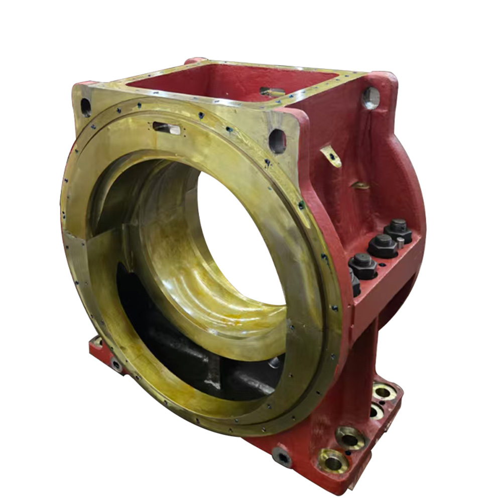
A Hydrodynamic sliding bearing supports radial loads and helps maintain intermediate-shaft position during operation. Bearing surface condition, dimensional fit, lubrication, and alignment should therefore be assessed when shaft symptoms indicate uneven support, abnormal journal contact, or unusual vibration.
The final inspection record should be more than a simple pass-or-fail statement. Record each defect in relation to shoulders, keyways, journals, flanges, bearings, and other relevant geometry. Its size, orientation, surface condition, and relationship with operating symptoms should also be documented. A condition map makes future repair decisions and repeat inspections substantially more useful.
Repair or Replacement: What Should Drive the Decision?
Finding damage does not automatically mean that repair is acceptable, and discovering a small defect does not automatically mean the entire shaft must be replaced. The central question is whether the defect can be completely removed while preserving the geometry, remaining load-bearing section, surface condition, and dimensional relationships required for continued service.
Crack Location Can Matter More Than Visible Length
Damage near a keyway, shoulder, coupling interface, heavily loaded journal, or other stress-concentrated area can carry greater fatigue significance than a similar-sized defect in a less critical region. Crack depth and orientation also matter because a defect extending into the primary load-bearing section cannot be judged from visible surface length alone.
Corrosion Repair Must Account for Dimensional Loss
Machining or polishing can remove corrosion pits and improve surface condition, but removing material also changes local dimensions. If sufficient cleanup affects a journal fit, shaft diameter, transition geometry, or alignment relationship, producing a visually clean surface does not necessarily make the shaft acceptable for continued service.
Before deciding that corrosion can be removed by machining, confirm how much material must be taken away and whether the resulting dimensions remain compatible with bearings, seals, couplings, and other mating components.
Previously Repaired Areas Require Additional Scrutiny
A previous repair should not automatically justify another repair using the same method. Grinding, machining, welding, or other restoration processes can influence geometry, surface finish, residual stress, and future inspection accessibility.
If repair creates new machining marks, sharp transitions, local notches, or dimensional inconsistencies, these areas can become future fatigue initiation sites under cyclic loading. Post-repair inspection should therefore verify both defect removal and the condition created by the repair itself.
When Replacement Becomes More Appropriate
Replacement generally becomes more compelling when cracking is extensive, multiple defects interact, removing the damaged material would create excessive dimensional loss, critical geometry cannot be recovered reliably, the shaft is significantly distorted, fitted surfaces are seriously damaged, or the initiating failure condition cannot be confidently eliminated.
Repair is more defensible when the defect has been clearly characterized, can be completely removed within permitted dimensional limits, and the repaired component can be verified for geometry, surface integrity, and compatibility with the rest of the shaft line.
Preventing Recurrence After the Immediate Damage Is Fixed
An effective failure response should remove both the damage and the condition that created it. Replacing a fractured shaft while retaining poor alignment, abnormal bearing loading, unsuitable coupling fit, inadequate surface protection, or damaging vibration merely restarts the same deterioration process on a new component.
Maintenance planning should combine periodic physical inspection with condition trends. Changes in vibration, bearing temperature, lubrication condition, shaft runout, corrosion, and coupling behavior are more useful when they can be compared with earlier measurements. A developing trend often provides more diagnostic value than a single reading taken without historical context.
Inspection intervals should also respond to service severity rather than rely entirely on fixed calendar periods. Seawater ingress, repeated heavy maneuvering, persistent abnormal vibration, propeller impact, grounding, or recent shaft-line work can justify an earlier examination because these events may change shaft loading or surface condition.
Specification control is equally important when replacement becomes necessary. Shaft material, heat treatment, main dimensions, transition radii, journal finish, coaxiality, coupling fit, inspection requirements, and mating-component information should be evaluated as one specification package.
Selecting a replacement shaft only by diameter or nominal torque can overlook the geometric, alignment, and support conditions that influence actual fatigue performance. Several parameters must be considered together because no single dimension can establish whether a replacement shaft will operate correctly within an existing propulsion line.
Traceable inspection records should also be retained. Photographs, defect maps, runout measurements, alignment data, nondestructive examination results, bearing observations, and final repair dimensions allow later inspections to distinguish between stable conditions and progressive deterioration.
Conclusion
Understanding marine propeller shaft failure causes requires more than examining the final fracture surface. Fatigue, corrosion, vibration, misalignment, surface damage, bearing support, and previous repairs can interact long before final failure occurs. Inspection should therefore prioritize changing operating symptoms and high-stress locations, then connect local defects to the complete propulsion shafting system.
Shanghai TOTEM Machinery Co., Ltd. is a manufacturer and supplier of marine shafting and related support components. Careful specification, dimensional control, and system-level inspection can help shipowners, shipyards, and MRO teams make more reliable repair-or-replacement decisions and reduce the risk of repeated shaft damage.
FAQ
What are the most common marine propeller shaft failure causes?
Common causes include cyclic fatigue, corrosion pitting, shaft misalignment, excessive vibration, stress concentration, surface damage, connection-fit problems, bearing deterioration, and defects introduced during machining or repair.
Can a propeller shaft crack exist without obvious vibration?
Yes. An early fatigue crack can develop locally without immediately producing strong vibration, so normal vibration behavior alone cannot confirm that critical shaft areas are crack-free.
Where should propeller shaft crack inspection focus first?
Priority areas include keyways, shoulders, fillets, coupling regions, journals, corrosion pits, fretted surfaces, machining damage, previous repair areas, and locations associated with abnormal bearing or alignment conditions.
Does corrosion always mean a marine shaft must be replaced?
No. The decision depends on corrosion depth, location, remaining dimensions, crack presence, and whether damaged material can be removed without compromising required geometry or load-bearing section.
Should bearings be inspected after a propeller shaft failure?
Yes. Bearing condition and shaft alignment are closely connected. Uneven support, lubrication problems, abnormal wear, or changed bearing loading can contribute to shaft bending, vibration, and recurring fatigue damage.
