
Views: 0 Author: Site Editor Publish Time: 2026-08-15 Origin: Site
High vibration alarms and failed outage inspections demand immediate attention. Engineers often face severe rotor distortion during these critical operational moments. Uncorrected shaft deviations lead to catastrophic internal rubbing and unexpected bearing failures. You also risk unplanned outages and severe mechanical degradation over time. Choosing an incorrect repair method introduces dangerous metallurgical flaws into the base material. You must avoid these irreversible errors.
This article provides a comprehensive technical evaluation framework. We help you diagnose steam turbine rotor bow and shaft runout accurately. You will discover how to assess various repair methodologies effectively. We explore ways to mitigate long-term reliability risks during major equipment overhauls. We guide you through precision measurements, root cause analysis, and quality control verification. You will learn exactly how to restore your rotating equipment safely.
Differentiating between temporary (thermal) and permanent (mechanical) rotor bow is the critical first step before committing to physical interventions.
Runout measurement must account for the strict tolerance thresholds at the journal and the DIN Sliding Bearing interface to restore hydrodynamic stability.
Repair methods—ranging from thermal hot-spotting to mechanical peening—carry distinct metallurgical risks that must be weighed against outage duration and replacement costs.
Selecting an MRO (Maintenance, Repair, and Operations) partner requires verifying their capability to perform stress-relieving and low-speed/high-speed balancing post-repair.
Framing the problem remains your primary technical responsibility. You must establish whether the distortion represents a reversible operational issue. Sometimes, it indicates permanent material deformation. Misdiagnosing this condition leads to disastrous repair attempts. You must separate transient thermal events from irreversible physical yielding.
Uneven cooling during turning gear operation causes temporary warping. Gravity acts constantly on a hot, stationary rotor. Hot air rises inside the casing space. The upper half of the rotor stays hotter and expands more. This dynamic bows the shaft upward. Water induction also causes sudden and violent thermal shock. Cold water hits hot metal unexpectedly. This forces rapid surface contraction on the lower half. The shaft bows downward violently.
Asymmetrical heating occurs frequently due to HP/IP/LP Turbine Casing distortion. Localized internal rubbing generates immense, uneven friction heat. This localized heat causes rapid thermal expansion at the rub site. The expansion increases the shaft bow further. The increased bow causes harder rubbing. Industry experts call this destructive spiral the Newkirk effect.
Material creep and fatigue develop over extended operational lifecycles. High temperatures and continuous dynamic stresses permanently alter the metal. Severe imbalance creates high radial loads during turbine operation. Over time, these cyclic forces permanently distort the geometry. Foreign object damage (FOD) directly impacts the rotating system. High-velocity impacts bend delicate components instantly. Severe radial rubs can permanently yield the Steam Turbine Rotor Shaft.
Ensure accurate root-cause identification before taking corrective action. This verification prevents applying mechanical repairs to a thermal problem. You could irreparably damage the rotor otherwise. Always verify temperature uniformity across the forging. Do this before taking any baseline mechanical measurements. You must allow the unit to reach ambient temperature naturally.
Quantifying the severity of the bow is absolutely essential. This accurate data informs your critical repair-or-replace decision. You need exact measurement figures to proceed safely. Engineers cannot rely on visual inspections alone.
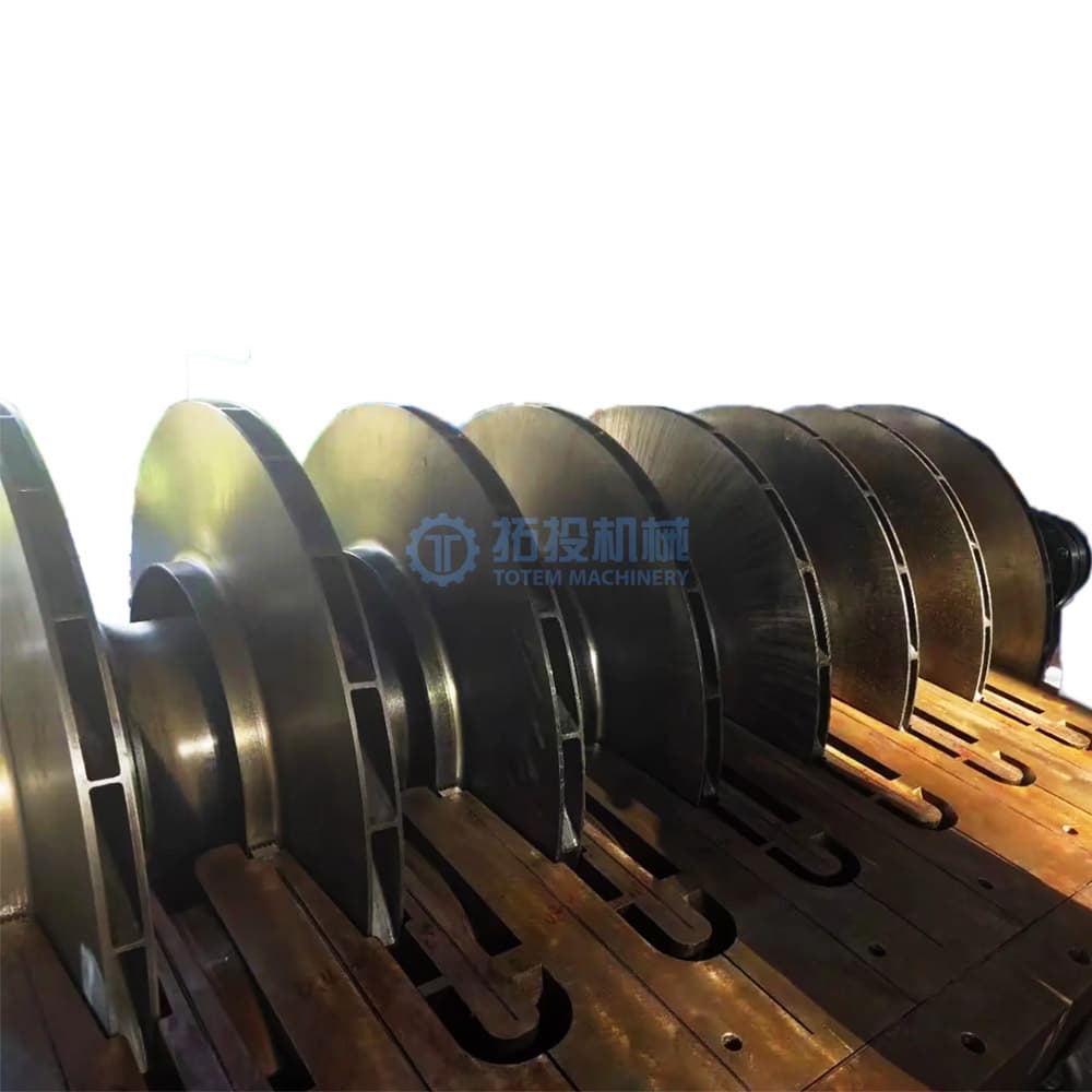
Engineers typically use precision dial indicators. They mount these instruments on V-blocks or lathe supports. These setups provide a stable measurement foundation. Proximity probe data offers dynamic operational insights during runtime. You must document the Total Indicator Reading (TIR) accurately. Record these readings across multiple axial locations along the shaft.
Follow this precise measurement procedure:
Isolate the rotor from all external thermal influences.
Mount calibrated dial indicators securely on a rigid base.
Rotate the shaft at slow, consistent speeds manually.
Record peak-to-peak amplitude at designated critical journals.
Map the entire shaft profile to identify the maximum deflection point.
Measure runout at the coupling and mid-span sections carefully. Bearing journals demand the highest level of dimensional scrutiny. You must assess the impact of current TIR levels. High eccentricity destroys the oil wedge integrity. This crucial wedge operates within a DIN Sliding Bearing. Hydrodynamic stability relies entirely on maintaining this microscopic radial clearance.
Compare field data against established ASME guidelines. Check specific OEM tolerances carefully for your unit. This establishes a clear pass/fail baseline for the equipment. Acceptable journal limits often fall well below 0.001 inches. High-speed flexible rotors demand even tighter tolerances. You must consider the rotor mass and operating speed. We outline standard tolerance thresholds below.
| Measurement Location | Standard OEM Tolerance (Inches) | Critical Action Threshold (Inches) | Operational Impact |
|---|---|---|---|
| Bearing Journals | 0.0005 - 0.0010 | > 0.0020 | Babbitt wiping, extreme vibration |
| Mid-Span / Belly | 0.0020 - 0.0040 | > 0.0080 | Seal rubbing, clearance loss |
| Coupling Faces | 0.0005 - 0.0015 | > 0.0030 | Alignment failure, coupling stress |

Structure the available engineering interventions carefully. Base your choice on the severity of the TIR. Consider the exact location of the maximum bow. We evaluate four primary repair options to restore operational geometry.
Apply localized, controlled heat to the convex side of the bend. This forces the material to yield predictably under compression. Controlled cooling then pulls the shaft straight as it shrinks. We find this highly effective for addressing deeper, severe bows. However, it requires expert metallurgical oversight. You must avoid altering the alloy's critical grain structure. Overheating causes irreversible carbide precipitation.
Peen the concave side of the shaft surface. Technicians use specialized pneumatic hammers for this procedure. This action induces powerful compressive stresses in the skin layer. These stresses physically straighten the rotor over time. It represents a faster, lower-heat correction method. We consider it primarily viable for superficial surface bows only. It cannot correct deep structural deformations.
Skim the shaft to create a completely new true centerline. Machinists use precision grinding tools for this exact task. This guarantees a perfectly concentric rotating surface. However, you permanently remove essential base material from the forging. You might require undersized bearings or custom seals afterward. We advise caution, as reducing journal diameter lowers load capacity.
Sometimes, you must scrap the yielded rotor completely. You then source entirely new Steam Turbine Parts. This carries the highest capital cost by far. It also involves the longest project lead time. Yet, it represents the absolute lowest technical risk. We recommend this exclusively for severely yielded or cracked shafts.
| Repair Method | Primary Application | Process Speed | Metallurgical Risk | Post-Repair Requirement |
|---|---|---|---|---|
| Thermal Straightening | Severe permanent bows | Slow | High (Heat Affected Zones) | Strict Stress Relieving |
| Mechanical Peening | Minor surface bows | Fast | Low | Surface Polishing |
| Machining / Grinding | Eccentricity at journals | Medium | None | Custom Bearings |
| Replacement | Catastrophic yielding | Very Slow | None | Full Re-commissioning |
Address the realities of physical rotor interventions directly. Pitfalls exist at every stage of the repair process. You must manage these execution risks proactively. Poor quality control destroys expensive rotating equipment instantly.
A straightened rotor can easily "remember" its original bow. It might revert to a bent state at high operational temperatures. You must perform proper Post-Weld Heat Treatment (PWHT) or thermal stress relieving. We use localized heating blankets for this crucial step. They raise temperatures to specific stress-relief points safely. Neglecting stress relieving guarantees future operational failures.
Thermal straightening introduces severe heat variables into the alloy. You risk material embrittlement and dangerous micro-cracking. Hardness alterations often occur in the localized heat-affected zones. Monitor temperature gradients meticulously during the entire repair process. We require constant thermocouple feedback to prevent overheating.
Mandatory Non-Destructive Testing (NDT) is completely non-negotiable. Use magnetic particle inspection (MPI) directly after straightening. This detects surface-breaking flaws. Ultrasonic testing (UT) verifies deeper structural integrity completely. It finds subsurface voids caused by the bending stress.
Both low-speed and operating-speed balancing are necessary. You cannot skip this step. High-speed vacuum balancing ensures dynamic stability before reinstallation. We test rotors at full operating speed in a bunker. This proves the bow will not return under centrifugal force.
Vet service providers rigorously for critical rotor interventions. Not all machine shops can handle severe metallurgical corrections. You need specialized engineering expertise for this high-stakes task. Ask demanding questions before signing any repair contract.
Assess their heavy machinery and floor space thoroughly. Do they possess necessary heavy-duty lathe capacities? Check for advanced horizontal boring mills. Verify they have operational vacuum balancing bunkers for your specific rotor class. A standard shop cannot test high-speed flexible rotors properly.
Ask about their internal engineering workflows. Do they perform in-house finite element analysis (FEA)? They must conduct metallurgical testing before attempting a thermal straighten. Guesswork leads to catastrophic rotor destruction. They need to understand the exact alloy composition before applying heat.
Demand total transparency from your chosen MRO partner. Expect clear "As-Found" and "As-Left" TIR documentation. Request comprehensive material hardness reports for your permanent files. We recommend inspecting the facility personally during the repair.
Look for vendors who easily provide the following:
Guaranteed runout limits post-repair.
Documented histories of similar rotors they successfully straightened.
Sample quality control packages and calibration certificates.
Request a comprehensive root-cause failure analysis (RCFA). Require a detailed repair feasibility study from their engineering team. Do this before approving any shop work. You must understand exactly why the bow happened initially. Otherwise, you will repeat the failure after reinstallation.
Addressing steam turbine rotor distortion remains a critical decision-point. You must balance outage downtime and long-term mechanical reliability carefully. Precision measurement drives successful repair outcomes every time. Strict adherence to OEM and industry tolerances guides your methodology safely. Never compromise on dimensional inspections.
Partner exclusively with competent MRO facilities. They must provide verifiable engineering analysis for every step. Avoid treating rotor straightening as a routine mechanical exercise. It is a highly complex metallurgical intervention.
Take these immediate action steps:
Isolate the equipment entirely and allow internal temperatures to equalize.
Perform multi-point TIR measurements using calibrated proximity probes and dial indicators.
Commission a full metallurgical assessment before choosing a thermal or mechanical straightening method.
Demand high-speed vacuum balancing documentation before accepting the repaired unit.
A: A thermal bow resolves naturally once internal temperatures equalize. Engineers often achieve this via continuous turning gear operation. A permanent bow involves plastic deformation of the metal. This severe condition requires extensive mechanical or thermal repair interventions.
A: Acceptable TIR depends on the rotor's speed and mass. You must also consult specific OEM specifications. However, typical tolerances fall within stringent micro-measurements. Journals generally require TIR limits strictly between 0.0005 and 0.002 inches.
A: No. Excessive bows often prevent safe straightening procedures entirely. Pre-existing material fatigue limits your repair options significantly. Severe metallurgical changes may force a full component replacement rather than a repair.
A: Eccentricity disrupts the critical hydrodynamic oil film. This disruption causes extremely high mechanical vibration. It generates excessive localized heat rapidly. Ultimately, it causes rapid wear or catastrophic wiping of the bearing babbitt.


