
Views: 0 Author: Site Editor Publish Time: 2026-08-07 Origin: Site
A marine shaft coupling can look serviceable while fatigue damage is already developing at a keyway, fillet, flange transition, bolt-hole edge, or corroded surface. Repeated torsional loads, small alignment errors, pitting, fretting, and local geometric stress raisers can combine until a small crack becomes a propulsion risk. Effective diagnosis therefore requires more than locating the visible fracture. It requires checking how the flange fits, how the shaft runs, how the bolts share load, and whether crack indications extend below the surface before deciding between repair and replacement.
Marine couplings transmit torque through geometry that inevitably contains changes in section: shaft-to-flange transitions, fillets, keyways, bolt holes, pilots, and other mating features. These locations do not necessarily cause failure by themselves, but they can raise local stress. Under repeated torque reversals, maneuvering cycles, vibration, bending, or fluctuating propeller loads, a small surface discontinuity at one of these locations can become a fatigue initiation point.
Fatigue should not be confused with a single overload event. An overload fracture generally results from one load exceeding the component's immediate capacity. Shaft coupling fatigue develops progressively as repeated stress grows a crack over many cycles, potentially while nominal operating torque remains below the level associated with gross yielding.
Corrosion makes this process more dangerous because a pit behaves like a small notch. Fretting can have a similar effect at poorly seated or microscopically moving interfaces. Once a crack initiates, every load cycle can extend it farther into the section. This is why coupling flange cracks should trigger inspection beyond the visible crack tip rather than simple surface grinding.
The geometry of the connected shaft is equally important. On a forged intermediate shaft, the flange, journals, shaft body, and mating regions must function as one geometric system. Dimensional accuracy, coaxiality, surface condition, and runout directly affect how the connected shaft line behaves after assembly.
A useful failure investigation therefore asks two questions simultaneously: where did the fatigue crack start, and what repeatedly loaded that location? Finding only the crack identifies the damage. Finding the stress mechanism is what prevents recurrence.
Misalignment and runout are related but should not be treated as interchangeable conditions. Alignment describes the relationship between shaft centerlines and their supporting system. Runout describes the measured deviation of a rotating surface from its intended geometric axis or plane. A shaft line may therefore require checks of both alignment and the actual geometry of the coupling face, rim, journals, and adjacent shaft sections.
If a flange face has excessive axial runout, the mating faces may not load uniformly. If the flange or shaft runs eccentrically, rotating forces can introduce repeated bending or uneven bearing reactions. A shaft alignment error can add further cyclic loading. For this reason, shaft alignment should be evaluated as part of the complete propulsion shafting system rather than as an isolated coupling measurement.
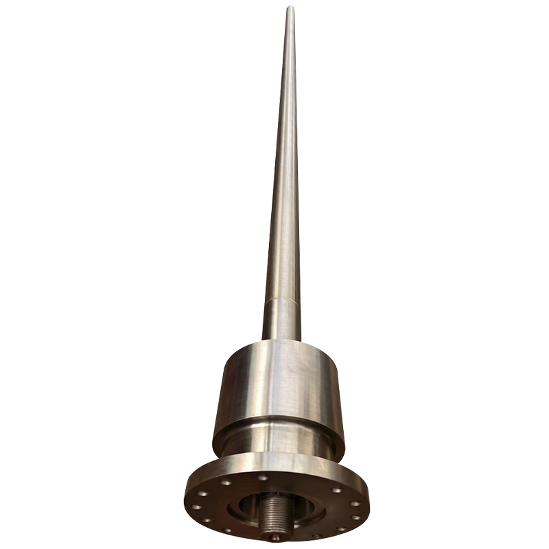
The same principle applies to a marine propeller shaft. Its shaft body, coupling connection, propeller mounting end, bearings, and seals must remain correctly related geometrically. Continuous high-torque and alternating loads make dimensional control at coupling interfaces especially relevant to stable transmission.
Bolted flanges add another layer. Torque should not be assumed to distribute perfectly among all bolts simply because every fastener is installed. Loose fasteners, inconsistent tightening, fretting around holes, damaged fitted surfaces, elongated holes, contamination between mating faces, or dimensional mismatch can alter load sharing. One highly loaded hole or flange region may then experience greater cyclic stress than the nominal design calculation suggests.
For troubleshooting, flange-face runout, radial runout, bolt-hole condition, mating-face contact, shaft alignment, bearing condition, and fastener condition should be evaluated together. Correcting only one indicator—for example, adjusting alignment without investigating distorted flange geometry—can leave the actual fatigue driver in place.
Operating condition also matters. Hull deflection, bearing wear, temperature changes, loading condition, previous grounding or propeller impact, and foundation movement can change shaft-line behavior after an originally acceptable installation. Inspection records are therefore more useful when measurements are compared under known vessel conditions rather than treated as isolated numbers.
A useful marine coupling inspection moves from simple observations to dimensional measurements and then to suitable NDT. The objective is not merely to declare a coupling cracked or uncracked, but to establish the crack location, extent, likely loading mechanism, and condition of the surrounding shaft line.
| Inspection Area | Practical Method | What It Can Reveal | Follow-Up When Abnormal |
|---|---|---|---|
| Flange, fillet, keyway, and exposed surfaces | Cleaning and detailed visual examination | Pitting, fretting debris, corrosion, scoring, rust bleed, impact marks, or visible cracks | Mark affected locations and expand inspection with appropriate NDT |
| Flange face and rim | Dial indicator or approved precision measurement method | Face wobble, eccentricity, distortion, seating problems, or questionable machining geometry | Separate flange error from shaft alignment and shaft runout |
| Bolt holes and fasteners | Dimensional examination and fastener-condition review | Hole elongation, fretting, damaged fits, loose load paths, or abnormal contact patterns | Verify design dimensions and approved fastening requirements before reuse |
| Shaft line and bearings | Alignment measurements plus bearing and support inspection | Angular or offset errors, support changes, abnormal bearing reactions, or connected-system movement | Correct the underlying support or alignment condition before final coupling work |
| Surface crack examination | MT on suitable ferromagnetic material or PT where appropriate | Surface-breaking and near-surface crack indications | Record position and orientation; determine whether deeper examination is required |
| Internal examination | UT where geometry and material permit | Subsurface discontinuities and the possible depth or extent of suspect regions | Map indications and assess against applicable engineering acceptance criteria |
Surface preparation is critical. Heavy corrosion, paint, oil, or rough grinding can interfere with inspection quality. NDT should also be selected for the material and defect type: magnetic particle testing is useful for suitable ferromagnetic components, penetrant testing detects surface-breaking defects, while ultrasonic examination can provide information about internal discontinuities when component geometry permits.
Crack orientation deserves attention because it may indicate the dominant loading direction. A crack following a flange transition, emerging from a keyway, or extending from a bolt hole should be considered together with local stress geometry. Multiple small indications distributed around a highly stressed region may indicate a different problem from one isolated handling mark.
Dimensional results should also be cross-checked. A low runout reading does not prove that bolt-hole fits are acceptable, and acceptable bolt holes do not prove the shaft is aligned. Likewise, finding a crack through NDT does not identify whether the initiating mechanism was corrosion, torsional cycling, bending, poor fit, or a combination. Effective marine coupling inspection combines these findings before a root-cause conclusion is made.
The repair-versus-replacement decision should begin with crack location and structural significance rather than crack length alone. Damage in a low-stress, non-critical surface area may have a different engineering consequence from a crack at a flange fillet, keyway, bolt-hole ligament, or shaft-to-flange transition. Removing material from a high-stress location simply to eliminate an indication can create a new geometry problem or reduce the available section.
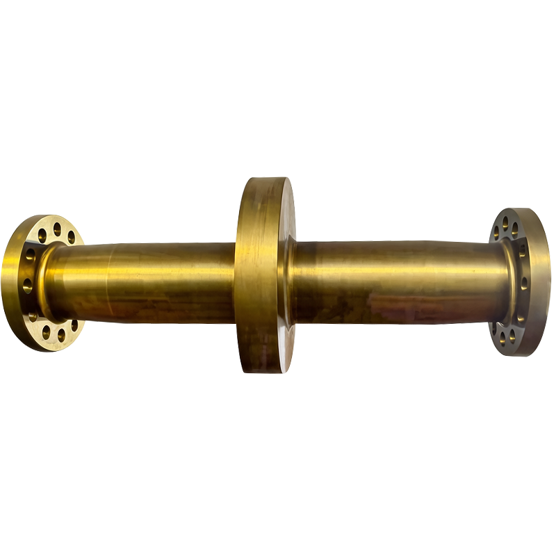
Replacement deserves stronger consideration when cracks enter a primary torque-transmitting section, multiple fatigue origins are detected, flange geometry is permanently distorted, bolt-hole damage compromises the intended fit, or repair would require substantial removal of material. Welding a critical shaft or coupling region should never be treated as an automatic field solution; material grade, prior heat treatment, residual stress, fatigue strength, approved repair procedures, and applicable classification requirements all affect whether such a repair is technically acceptable.
Where replacement is selected, ordering only by shaft diameter and overall length is insufficient. A new forged propulsion shaft or other shaft segment must be matched to the actual load path and drawing requirements. Forged shaft manufacture can involve controlled material selection, heat treatment, precision machining, and inspection of critical mating geometry.
Before a replacement shaft or coupling is released for manufacture, confirm the flange outside diameter, thickness, pilot or spigot geometry, bolt circle, hole dimensions and fit requirements, shaft diameters, transition radii, keyway details, mating interfaces, specified material, heat-treatment requirements, face runout, radial runout, coaxiality, surface-finish tolerances, required NDT methods, acceptance criteria, documentation requirements, and the relationship with adjacent bearings, seals, shaft sections, and coupling components.
Repair is only successful if the original loading mechanism is removed. Installing a new flange onto a shaft line with unresolved bearing wear, alignment error, distorted mating geometry, or incorrect bolt loading can reproduce the same failure mechanism on a new component.
Prevention starts at specification. Coupling transitions should follow approved geometry, machined surfaces should avoid avoidable stress raisers, mating dimensions must support the intended fit, and inspection requirements should be stated before manufacture rather than added after damage appears. Surface finish, fillet geometry, bolt-hole quality, corrosion protection, runout, and coaxiality should be considered together because fatigue reliability depends on the combination, not one isolated tolerance.
Installation is equally important. Mating faces should be clean and free of burrs or trapped debris. Runout should be checked before final assembly when required, and bolts should be installed using the approved tightening or preload procedure for the particular joint. Shaft alignment should be verified under the vessel conditions specified by the designer, yard, equipment supplier, or classification requirements. If bearing work, foundation work, shaft removal, collision damage, or major dry-docking repairs have occurred, previous alignment assumptions should not automatically be reused.
Operational monitoring helps identify changes before coupling flange cracks become obvious. Increasing vibration, repeated bearing temperature changes, unusual seal behavior, fretting products near a coupling, abnormal noise, recurrent fastener problems, or changes following propulsion impact are reasons to expand inspection beyond the symptom itself. A coupling may be where the damage becomes visible even though the initiating condition originated elsewhere in the shaft line.
The connected marine propulsion parts include intermediate shafts, propeller shafts, thrust shafts, bearings, seals, and coupling-related components. Their mechanical relationship means a coupling inspection should not stop at the flange boundary.
Finally, preserve useful maintenance history. Runout readings, alignment data, NDT indication maps, bearing condition, bolt observations, operating symptoms, and previous repairs create a baseline for later comparison. A trend showing gradual change is often more informative than one measurement taken after a failure has already developed.
Marine shaft coupling failure is best prevented by treating the coupling as part of a loaded shaft line rather than an isolated flange. Fatigue cracks become more understandable when stress concentration, corrosion, fit, runout, bolt load sharing, and alignment are evaluated together. Inspection should combine dimensional checks, suitable NDT, and root-cause analysis before repair or replacement is approved. Shanghai TOTEM Machinery Co., Ltd. is a manufacturer of forged and machined shaft components where mating geometry, coaxiality, surface condition, and inspection control are important to reliable propulsion-system integration.
A: Common causes include cyclic torsional or bending stress, stress concentration, corrosion pits, fretting, poor flange fit, shaft misalignment, excessive runout, fastener problems, and combinations of these conditions.
A: It depends on crack location, depth, material, flange geometry, remaining section, repair method, and approval requirements. Cracks in highly stressed torque-transmitting regions often require more conservative evaluation.
A: Magnetic particle testing can detect surface and near-surface flaws in suitable ferromagnetic materials, penetrant testing finds surface-breaking defects, and ultrasonic testing can evaluate internal discontinuities where geometry permits.
A: Excessive face or radial runout can create uneven loading, vibration, bending forces, and poor flange contact, increasing cyclic stress at transitions, fasteners, bearings, and other fatigue-sensitive locations.
A: Confirm material, heat treatment, flange dimensions, bolt-circle geometry, hole fits, keyways, transition radii, shaft interfaces, runout and coaxiality tolerances, surface finish, NDT requirements, and applicable approval documentation.


