
Views: 0 Author: Site Editor Publish Time: 2026-08-17 Origin: Site
A broken connecting rod is rarely an isolated incident. It is typically the final, catastrophic result of systemic mechanical or operational stress. When this critical component fractures, operations halt immediately. Ignoring early warning signs almost always leads to massive equipment overhauls.
For maintenance and reliability engineers, diagnosing a reciprocating compressor connecting rod failure requires separating the symptom from the root cause. You must trace the failure path accurately. Doing so helps prevent catastrophic collateral damage to vital adjacent components.
This guide outlines the evidence-based causes of rod failure. We detail precise inspection protocols for early detection. You will also learn the technical criteria required when evaluating replacement components. Understanding these mechanical relationships ensures long-term operational reliability for your compression systems.
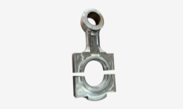
Root Cause Identification: Most failures stem from lubrication starvation, severe misalignment, or liquid carryover (hydro-locking), rather than standalone material defects.
Inspection Mandates: Effective prevention requires integrating Non-Destructive Testing (NDT) and precise dimensional run-out checks during scheduled turnarounds.
Replacement Criteria: Upgrading to an alloy steel connecting rod is only effective if system-level alignment and lubrication baseline requirements are concurrently addressed.
Procurement Standard: Evaluating aftermarket or OEM gas reciprocating compressor parts requires strict adherence to metallurgical certifications and dimensional tolerances.
We cannot view rod failure merely as a broken part. It acts as a primary trigger for severe operational disruption. A single fracture halts gas flow immediately. This event triggers unplanned outages and severe production bottlenecks. In volatile environments, sudden mechanical separation also elevates hazardous gas release risks. You face immediate safety concerns alongside production losses.
Systemic damage rarely stops at the rod itself. When separation occurs during a high-speed compression stroke, the machine transfers extreme kinetic energy outward. This force violently impacts the Compressor Crankshaft. Engineers routinely observe severe journal scoring following a rod fracture. In worst-case scenarios, the kinetic shock bends the crankshaft entirely. It may even cause total web failure.
Adjacent mating components suffer equally. The uncontrolled rod movement strikes the crosshead housing. It causes immediate misalignment. Pistons drag against cylinder walls. This dragging creates deep scoring across the cylinder bores.
You must establish a strict evaluation baseline before planning repairs. Any repair versus replace decision requires comprehensive inspection of all adjacent components. Replacing the rod alone guarantees future breakdowns. You must measure crankshaft run-out, verify crosshead integrity, and bore-scope the cylinders. Addressing collateral damage prevents repeat failures.
Understanding failure mechanics helps you prevent future occurrences. Component fracture happens for distinct, measurable reasons. We categorize these root causes into four primary areas.
Lubrication Breakdown (Thermal & Friction Fatigue)
Clean oil maintains a hydrodynamic film at the crankpin and crosshead pin bearings. Losing this fluid film creates immediate metal-to-metal contact. Friction spikes exponentially. Temperatures rise rapidly in the bearing shells. Contaminated oil also introduces abrasive wear. Particulates gauge the bearing surfaces. This clearance degradation introduces a severe rod knock. The repeated impact forces eventually fracture the rod eye.
Abnormal Loading & Hydro-Locking
Compressors process gas, not liquid. Liquid carryover in the gas stream creates a devastating condition. We call this hydro-locking. Liquids are incompressible. When the piston attempts to compress a fluid slug, it meets an immovable barrier. This creates an instantaneous compressive buckling force. The rod either buckles instantly or snaps under severe tensile stress on the return stroke. Faulty suction or discharge valves also cause severe over-pressurization. This mimics the stress of hydro-locking.
Mechanical Misalignment
Running gear must operate in perfect alignment. Improper crosshead-to-cylinder alignment induces cyclical bending stress. The rod flexes slightly during every single stroke. Millions of cycles later, fatigue cracking initiates. Frame distortion also contributes to this problem. Foundation settling transfers uneven loads directly through the running gear. You might notice accelerated packing wear just before the rod ultimately snaps.
Fastener Failure
The rod cap bolts endure massive tensile loads. Fastener yielding often precedes catastrophic separation. Improper torquing during maintenance is a frequent culprit. Under-torqued bolts allow cap separation and fretting. Over-torqued bolts exceed their yield strength. They lose elasticity and snap during standard operation. Once a bolt fails, the remaining bolt absorbs the entire load. It fails milliseconds later.
Catching degradation early saves the entire compressor frame. You must implement strict inspection protocols. We divide these into visual, non-destructive, and predictive monitoring strategies.
During scheduled turnarounds, you must measure bearing clearances accurately. Check both the crankpin and wrist pin locations. While plastigauge offers a quick visual reference, micrometers provide superior precision. Compare your measurements against exact OEM tolerances.
Engineers must also verify rod straightness. Measure the precise center-to-center distance between the big end and small end bores. Even a microscopic bend indicates prior fluid ingestion. A bent rod requires immediate rejection.
Magnetic Particle Inspection (MPI): This method identifies surface fatigue cracks. We focus heavily on the I-beam transition areas. You should also inspect the rod eyes and bolt spot-faces closely. MPI highlights microscopic defects before they propagate into full fractures.
Ultrasonic Testing (UT): Surface checks are not enough. UT detects internal metallurgical voids. It spots sub-surface crack propagation in high-stress zones. We recommend UT for all rods operating in high-pressure or corrosive gas environments.
You can predict failures while the machine runs. Vibration analysis is your first line of defense. Monitor crankcase velocity strictly. Sudden vibration spikes often indicate increasing bearing clearances.
Used oil analysis provides a chemical warning system. Trend your sample data carefully. Watch for sudden spikes in Babbitt, copper, or steel particulates. Babbitt flakes indicate bearing overlay wear. Copper indicates you have reached the bearing backing material. Steel particulates suggest the crankshaft or rod base material is actively degrading.
Table: Standardized Rod Inspection Protocols
| Inspection Type | Method/Tool | Target Defect | Recommended Frequency |
|---|---|---|---|
| Dimensional | Micrometer / Bore Gauge | Clearance degradation, ovality | Every major overhaul |
| Surface NDT | Magnetic Particle (MPI) | Surface fatigue, stress fractures | 24,000 to 40,000 hours |
| Internal NDT | Ultrasonic Testing (UT) | Sub-surface voids, casting flaws | Post-upset or major overhaul |
| Predictive | Oil Analysis & Vibration | Bearing wear, misalignment | Monthly / Continuous |
When a rod fails, replacement presents an engineering choice. Standard carbon steel components often fall short in demanding applications. Upgrading component metallurgy significantly improves reliability.
We strongly recommend specifying an Alloy Steel Connecting Rod for critical services. Forged 4140 or 4340 steel provides superior tensile strength. These alloys resist cyclical fatigue much better than standard carbon steels.
Heat treatment plays a vital role here. Quenching and tempering processes manipulate the steel's microstructure. This process achieves the exact yield strength required for heavy gas compression. It ensures the rod flexes slightly under load without permanently deforming.
Vendor machining capabilities matter immensely. Evaluate your vendors based on their adherence to strict surface finish requirements. We measure this in Ra (Roughness Average). Bearing bores must meet exact Ra specifications. A rough bore prevents proper bearing crush. It leads to premature bearing wipe and eventual rod knock.
You should also verify shot peening requirements. Shot peening bombards the rod surface with tiny metallic spheres. This introduces beneficial compressive stress to the outer layer. It acts as a barrier against surface crack initiation. It is mandatory for any true Heavy-Duty Connecting Rod.
Chart: Carbon Steel vs. Alloy Steel Performance Variables
| Performance Variable | Standard Carbon Steel (e.g., 1045) | Alloy Steel (e.g., 4140/4340 Forged) |
|---|---|---|
| Tensile Strength | Moderate (Adequate for light duty) | High (Resists severe operational spikes) |
| Fatigue Resistance | Baseline | Superior (Ideal for continuous cycling) |
| Heat Treatment Response | Limited core hardening | Deep, uniform hardness profile |
| Best Application | Low-pressure air compressors | High-pressure process gas compressors |
Sourcing reliable components requires strict vetting. When evaluating suppliers of Gas Reciprocating Compressor Parts, demand transparency. Always request Material Test Reports (MTRs). MTRs prove the chemical composition matches your specification. Ask for proven field hours in similar gas applications. Finally, review warranty terms carefully. Reputable manufacturers stand behind their metallurgical data.
Procuring a high-quality component is only half the battle. Installation dictates the component's ultimate lifespan. Poor installation practices ruin perfectly engineered parts.
We must transparently address the "Band-Aid" risk. Installing a high-performance alloy rod without correcting the foundational issue guarantees repeat failure. If inadequate lube pump pressure caused the original fracture, the new rod will also starve for oil. If foundation soft-foot caused severe misalignment, the new rod will bend and break. You must correct the baseline system mechanics first.
Precision matters during reassembly. Strict adherence to rod bolt stretch protocols is non-negotiable. Many mechanics still rely on torque wrenches. However, measuring actual bolt stretch provides true clamping force data. Follow the manufacturer's exact tightening sequence.
Before closing the crankcase, verify all crosshead clearances. You must also perform a complete crankshaft web deflection test prior to startup. This test ensures the new rod and bearing assembly has not introduced unnatural strain on the crankshaft journals.
A rebuilt running gear needs a controlled break-in period. Implement strict run-in procedures. Protocol dictates progressive loading. Do not jump immediately to 100% capacity.
Monitor bearing temperatures closely during the first 24 hours. Watch for abnormal heat spikes. Finally, schedule an initial oil filter inspection shortly after post-installation startup. Cutting open the oil filter reveals any rapid preliminary wear. Finding clean filter media gives you clearance for continuous heavy-duty operation.
Reciprocating compressor connecting rod failure requires a holistic evaluation of system mechanics. It is never just a simple parts swap. You must understand the thermal, mechanical, and operational loads applied to the running gear. By tracing the damage backward, you protect adjacent components and stabilize the entire machine.
Take proactive steps today to secure your equipment. Advise your maintenance stakeholders to audit current NDT inspection intervals. Analyze your most recent used oil samples for hidden wear metals. Finally, partner with component manufacturers who provide transparent metallurgical data and robust engineering support. These actions transform sudden catastrophic failures into manageable, scheduled maintenance events.
A: Uncharacteristic crankcase knocking is the most prominent audible sign. Predictive indicators include sudden spikes in velocity vibration data or the appearance of bronze and babbitt flakes in your oil filters. These suggest severe bearing clearance degradation.
A: Generally, no. Attempting to straighten a rod compromises its structural integrity permanently. The material retains residual stress from the initial bending event. Total replacement with a certified heavy-duty connecting rod is the industry standard for risk mitigation.
A: Typically, NDT occurs during major scheduled overhauls. This falls between 24,000 to 40,000 operating hours. However, you must perform NDT immediately following a process upset, such as a severe liquid carryover or over-pressurization event.
A: Only if the breakage is due to exceeding the original design duty cycle. If the root cause is misalignment, hydro-locking, or poor lubrication, even the strongest alloy will eventually fail. You must fix the system issue first.


