
Views: 0 Author: Site Editor Publish Time: 2026-08-03 Origin: Site
Vibration, premature bearing wear, seal problems, or difficulty aligning shaft-line flanges may lead to suspicion of a bent shaft, but symptoms alone cannot identify the cause. A reliable marine propeller shaft runout measurement requires the correct measuring surface, stable shaft support, controlled rotation, and readings from more than one location. The important question is not simply whether the dial indicator moves. It is what feature was measured, how the shaft was supported, where the high point occurred, and whether the recorded TIR exceeds the acceptance criterion for that specific shaft and installation.
Runout describes how a surface moves relative to an axis as the shaft rotates. Radial runout is measured on a cylindrical surface with the indicator acting approximately perpendicular to the shaft centerline. Axial or face runout is measured in the axial direction against a flange face or another surface intended to be perpendicular to the shaft axis. A complete revolution provides a maximum and minimum indicator value, and their difference is the Total Indicator Reading, or TIR.
These measurements answer different questions. Excessive radial movement at a journal may result from shaft bending, journal eccentricity, local surface damage, an unsuitable rotational reference, or support distortion. Face runout can indicate that a flange face is not square to its rotational axis, but it does not automatically prove that the entire shaft is bent.
Alignment is also different from runout. Alignment evaluates the relative position and angle of connected shaft-line components, bearings, or flange centers. A shaft can have acceptable local runout yet still be improperly aligned with an adjacent shaft. Conversely, an alignment operation cannot correct geometric runout that is physically present in the shaft or flange.
For a Marine Propeller Shaft, straightness, runout, coaxiality, journal dimensions, and flange geometry should therefore be evaluated as separate drawing requirements rather than treated as interchangeable indicators.
A dial indicator can produce very precise numbers while still giving a misleading result if the measurement setup moves. Before mounting the instrument, clean the measuring track and remove rust particles, dried protective coating, burrs, oil deposits, or other contamination that could lift the indicator tip. Inspect the surface visually as well; a scratch or isolated dent may create a local needle movement that should not be confused with overall shaft eccentricity.
The indicator base must reference a rigid structure that does not move with the shaft. Position the contact point so its motion follows the intended measuring direction, preload the indicator within its usable range, and verify that the stylus will remain in contact throughout 360 degrees of rotation. Slowly rotating a shaft through one full revolution and comparing maximum and minimum readings is the basic method used for shaft TIR measurement.
For an installed shaft line, record whether couplings are connected or separated, whether bearings are loaded, and whether auxiliary supports or jacks are being used. These conditions matter especially on long, heavy shafts. Their own weight, bearing clearances, coupling forces, and temporary support positions can influence the rotational condition being measured.
For a removed shaft measured in a workshop, the support arrangement is equally important. The shaft should be rotated using the reference condition required by the inspection plan, such as suitable centers, rollers, or defined journal supports. Changing support locations between inspections can change the reading, so a before-and-after comparison is only meaningful when the measurement condition is reproducible.
One dial indicator position cannot describe an entire large marine shaft. Measurement points should correspond to functional features and likely deformation zones. Begin with accessible machined cylindrical surfaces such as bearing journals and coupling-adjacent shaft sections. Add points toward the propeller end where practical, particularly after impact, handling damage, machining, or repair. On long shafting, several stations along the shaft body provide much more diagnostic value than a single measurement near one end.
The same principle applies to a Marine Intermediate Shaft. Its relationship with adjacent shafts, bearings, journals, and flange connections means that checking geometric accuracy only at one flange can miss a local or distributed deviation elsewhere along the shaft.
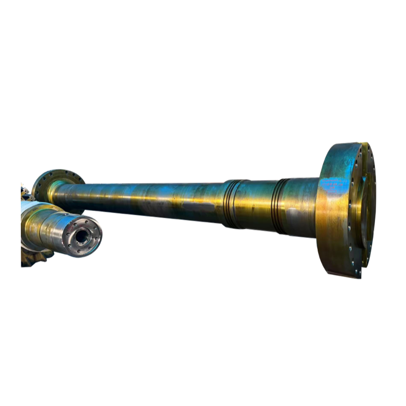
Flanges require two separate checks. For radial flange runout, place the indicator against a suitable cylindrical pilot, register, rim, or other drawing-defined radial feature. For flange face runout, point the indicator axially against the machined face, normally as far toward the usable outer measuring radius as the specification allows. Do not label these two readings simply as “shaft runout” on an inspection record; their causes and corrective actions can differ substantially.
Measurement locations should also be identifiable later. Rather than writing “middle” or “near coupling,” record a station from a fixed datum or identify the exact journal, flange, or diameter. Marking angular positions such as 0°, 90°, 180°, and 270° makes repeat measurements easier and helps determine whether high points at different stations share a meaningful angular relationship.
For each station, establish the shaft condition first, then rotate it slowly by hand through 360 degrees. Watch the indicator continuously rather than recording only four quarter-turn values; the true peak may fall between those positions. Note both the maximum and minimum readings and calculate:
TIR = Maximum indicator reading − Minimum indicator reading
Do not automatically divide TIR by two. Some engineering documents express deviation, eccentricity, or a particular acceptance criterion as one-half of TIR, while others specify allowable runout directly as full TIR. The drawing, inspection specification, class requirement, repair procedure, or equipment documentation must define which quantity is being limited.
Repeat the rotation before accepting the result. If the second reading differs significantly, inspect the indicator base, contact point, shaft support, surface condition, and rotational method before assuming the shaft itself changed.
A useful inspection record contains enough information to reproduce the check:
| Record Field | What to Capture |
|---|---|
| Measurement station | Journal, shaft body position, flange rim, or flange face |
| Shaft condition | Installed or removed, coupled or uncoupled, bearing and support condition |
| Indicator direction | Radial or axial |
| Maximum and minimum | Actual observed indicator values |
| TIR | Maximum minus minimum |
| High-point angle | Angular position of peak reading |
| Repeat result | Second full-rotation TIR |
| Acceptance criterion | Drawing or project-specific requirement |
| Disposition | Accept, investigate, recheck, repair, or replace |
Recording the high-point angle is particularly useful. A final TIR number tells how much variation exists, while the angular position and distribution of that variation help explain what may be creating it.
The first decision is whether the reading exceeds the applicable specification, not whether it exceeds a generic number found in another shaft application. Acceptable runout depends on the feature, diameter, shaft arrangement, measuring condition, machining requirement, and system design. A tolerance intended for a motor shaft or a small vessel should not automatically be transferred to a large marine propulsion shaft.
Next, examine the pattern across measurement stations. An isolated high reading at one journal deserves inspection for local eccentricity, damage, contamination, or machining error before concluding that the complete shaft is bent. Increasing radial TIR over several longitudinal stations may indicate a broader geometric deviation, but the support arrangement should be checked before making that diagnosis.
Similar angular high points at neighboring stations may support the possibility of a common bow or reference-axis error, whereas inconsistent high points can justify checking individual features and the measurement setup separately.
Flange results require their own interpretation. High face runout with relatively stable adjacent radial readings directs attention toward flange-face geometry, seating, perpendicularity, or coupling conditions. High radial runout at the flange register points toward a different geometric relationship. Treating either result as proof of “shaft misalignment” can send maintenance work in the wrong direction.
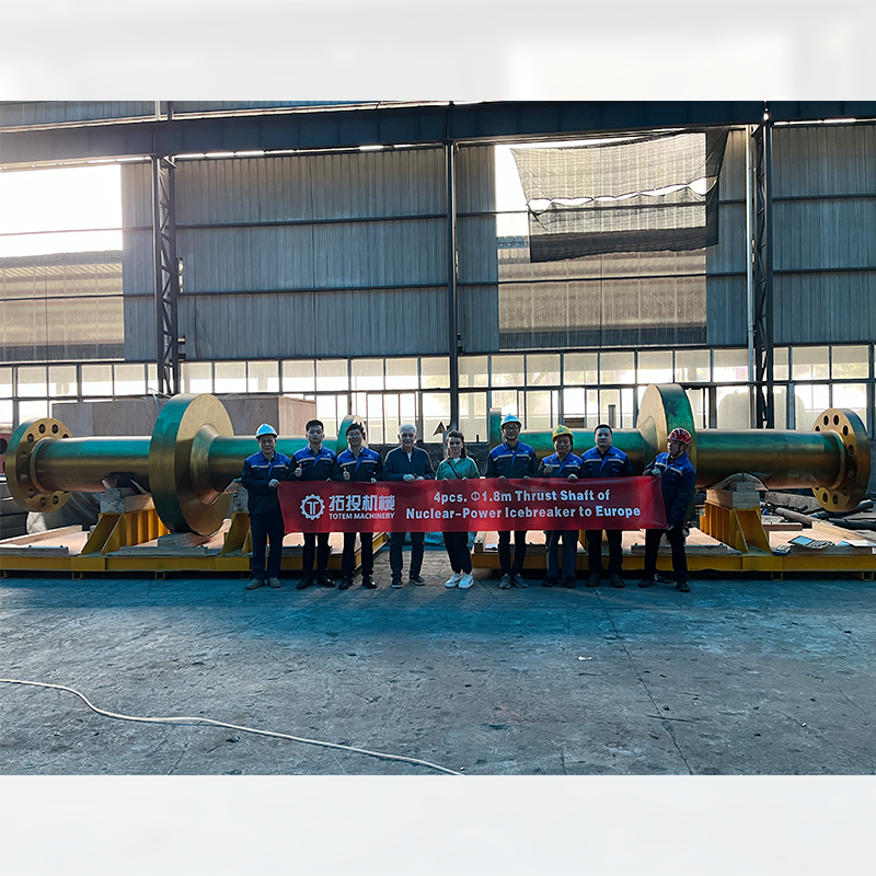
For a Forged Propulsion Shaft, geometric inspection can include runout together with dimensional calibration and other specified examinations. These controls should be considered together when determining whether machining, further inspection, or another corrective process is appropriate.
Bent marine shaft symptoms such as speed-related vibration, unusual bearing behavior, seal problems, or repeated alignment difficulty are reasons to investigate, not substitutes for measurement. These symptoms may be associated with shaft runout, but they can also result from bearing wear, coupling conditions, alignment errors, or other propulsion-system factors.
A practical corrective decision therefore follows the evidence: first repeat the measurement; then eliminate setup and support errors; compare multiple stations; separate radial from face results; inspect associated bearings, couplings, and mating surfaces; and finally compare the confirmed data with the applicable acceptance requirement. Straightening, re-machining, further non-destructive examination, or replacement should be considered only after the location and likely nature of the deviation are established.
Effective marine propeller shaft runout measurement depends more on measurement discipline than on obtaining a single dial-indicator value. Radial TIR, flange face runout, support condition, measurement location, and angular high points should be recorded and interpreted together before corrective work begins. Shanghai TOTEM Machinery Co., Ltd. is a manufacturer and supplier with machining and production capabilities for marine shaft components. Clear geometric and dimensional inspection requirements help connect shaft manufacturing accuracy with later alignment, installation, and maintenance decisions.
A: Mount a stable dial indicator against the specified surface, rotate the shaft slowly through 360 degrees, record the maximum and minimum readings, and subtract them to obtain TIR.
A: No. TIR can include bending, eccentricity, local surface error, support effects, and reference-axis variation. Measurements at several longitudinal positions are needed before diagnosing a bent shaft.
A: Useful locations include bearing journals, coupling-adjacent sections, accessible shaft-body stations, and propeller-end areas. Flange rims and flange faces should be recorded as separate measurements.
A: Radial runout measures movement perpendicular to the shaft axis on a cylindrical surface. Face runout measures axial variation of a flange or another perpendicular mating surface.
A: Repeat the measurement first, verify the instrument and supports, compare other stations, identify whether the deviation is local or distributed, and then determine the appropriate repair or replacement action.


