


Surface marks on an intermediate shaft can look minor while hiding a larger shaftline problem. Scoring may come from oil-film loss, but similar journal wear can also follow edge loading, contaminated lubricant, bearing deterioration, corrosion, or misalignment. The repair decision therefore cannot start with polishing or machining. It starts by identifying the damage pattern, measuring what material and geometry have actually been lost, checking for cracking or heat effects, and tracing the condition back through the bearing and support system. That sequence is the key to assessing marine intermediate shaft damage without treating symptoms as root causes.
Start With the Damage Pattern, Not the Repair Method
Surface appearance is valuable because it shows where contact, heat, corrosion, or relative movement has occurred. It is not enough, however, to classify a shaft as simply “scored” or “worn.” Before aggressive cleaning or polishing removes evidence, photograph the complete damaged zone, mark its axial and circumferential position, and record its relationship to bearing edges, journal shoulders, fillets, flange features, and other reference points.
A practical damage map can narrow the next inspection step:
| Damage Pattern | Possible Mechanism | Inspection Priority | Main Repair Concern |
|---|---|---|---|
| Circumferential grooves or shaft scoring | Abrasive particles, oil-film breakdown, bearing contact | Groove depth, journal diameter, bearing surface, lubricant condition | Material loss and final journal diameter |
| Local polished or wiped band | Concentrated bearing contact or edge loading | Contact position, bearing clearance, alignment, journal geometry | Localized heating and uneven wear |
| Heat discoloration or transferred bearing material | Severe friction or bearing distress | Surface cleaning, hardness comparison, NDT | Possible thermal or metallurgical change |
| Tapered or uneven journal wear | Persistent non-uniform bearing loading | Multi-station diameter measurements and bearing contact | Geometry and future bearing clearance |
| Corrosion or pitting | Moisture exposure or failed surface protection | Pit depth, location, NDT where necessary | Stress concentration and dimensional loss |
| Fretting near fitted or flange areas | Relative movement, fit problems, vibration | Mating surfaces, fasteners, runout and contact | Fit restoration rather than simple polishing |
Intermediate shaft journal wear must be interpreted by location as well as depth. A shallow mark across a broad, low-stress cylindrical area may present a different repair problem from a defect extending into a journal shoulder or transition. Corrosion pits, machining marks, or cracks near highly stressed geometric changes also deserve more attention than their visual size alone suggests.
Deposited bearing material can also make the journal look more severely damaged than the steel beneath it. Conversely, removing transferred material can expose deeper scoring. Initial cleaning should therefore preserve the original damage map and distinguish material transfer from actual loss of shaft base metal before dimensions are accepted.
Trace Damage Through Bearings, Lubrication, and Alignment
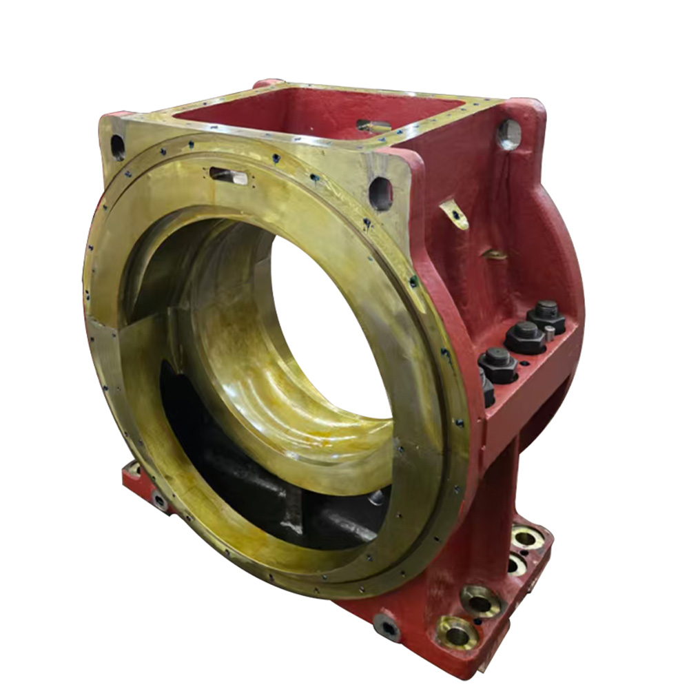
The shaft and its bearing should be treated as an interacting system. A hydrodynamic Marine Journal Bearing supports the intermediate shaft radially while its operating condition depends on journal geometry, bearing clearance, lubrication, rotational behavior, and load distribution. The bearing surface and shaft journal therefore provide evidence about each other rather than representing two independent inspection items.
Intermediate shaft misalignment can change the attitude of the journal within the bearing. Instead of distributing load over the intended working region, contact pressure can move toward one edge. Local pressure rises, the hydrodynamic oil-film margin decreases, and temperature can increase in a restricted area. Continued operation may then produce bearing wiping, transferred material, localized polishing, and shaft scoring.
The causal chain can also run in the opposite direction. Lubrication loss or bearing deterioration may damage the bearing first. As bearing material wears and clearance changes, shaft support can change, altering its working position and redistributing load to neighboring supports. A bearing failure can therefore create apparent alignment symptoms, while misalignment can itself initiate bearing failure. Moving a bearing to correct an alignment reading without first examining lubrication, clearance, bearing seating, and visible wear risks correcting the consequence instead of the cause.
Cold alignment data should not be treated as proof that the shaftline remains correctly loaded underway. Draft, cargo or ballast distribution, hull deformation, thermal growth, propeller forces, and machinery temperature can alter shaft-to-bearing relationships after the vessel leaves the static inspection condition. If damage appeared only at a particular load, speed, draft, or hot operating condition, that operating state should be recorded and considered during the investigation.
Measure Journal Geometry Before Deciding What NDT Means
A marine shaft repair inspection should establish geometry before deciding how much metal can safely be removed. Measuring only the minimum journal diameter is insufficient because the same minimum value can result from uniform wear, taper, ovality, a localized groove, or eccentric geometry. Those conditions require different corrective decisions.
A disciplined inspection sequence is:
Record the operating history, including recent bearing temperature changes, vibration, lubrication abnormalities, grounding or impact events, dry-dock work, bearing replacement, and alignment changes. Photograph and map the damaged surface before polishing alters the evidence.
Measure journal diameter at several axial stations across the working width. At each station, take measurements in multiple angular directions so ovality can be distinguished from general diameter loss. Comparing stations reveals taper, edge wear, and localized material removal.
Check shaft and journal runout at relevant cylindrical surfaces, and measure flange radial and face runout separately where required. Record both TIR and the angular position of the high point rather than treating one indicator value as a complete diagnosis.
Clean the defect sufficiently for nondestructive examination without unnecessarily removing base material. For suitable ferromagnetic shaft steels, magnetic particle inspection can identify surface and near-surface discontinuities. Other NDT methods should be selected according to shaft material, defect orientation, location, and the applicable inspection procedure.
Map hardness across the damaged region and compare the results with unaffected reference areas and the applicable material requirements. A localized hardness change after severe frictional heating can matter even when the surface can be machined clean.
Reinspect the bearing, housing, clearance, lubricant condition, support arrangement, and alignment evidence before finalizing the shaft disposition. A journal measurement describes the damage; it does not by itself explain why the damage occurred.
The measurement record should preserve actual values rather than only an “acceptable” or “reject” conclusion. Journal diameters, taper, ovality, runout, surface finish, defect location, NDT results, hardness readings, and inspection conditions create a baseline that can be compared with final post-repair measurements.
Surface roughness deserves the same treatment. A polished journal can look smooth while still having unacceptable taper or undersize diameter. Conversely, a geometrically acceptable journal may still require finishing to achieve the surface condition specified for its bearing system. Inspection of an intermediate shaft should therefore consider roughness, runout, magnetic particle inspection, and other nondestructive examination together rather than independently.
Set the Repairability Boundary Before Removing More Metal
Repairability is not defined by whether a machine can physically clean up the surface. It is defined by whether the resulting shaft can still satisfy the required dimensions, geometry, material condition, bearing interface, and inspection acceptance criteria.
Superficial scoring may be suitable for controlled polishing when the defect can be removed without meaningful dimensional loss and the required surface finish remains achievable. Deeper scoring or intermediate shaft journal wear may require grinding or machining to a reduced diameter. That option is only practical when the permitted final journal dimension is known and the corresponding bearing can be restored or manufactured to provide the required running clearance.
This is why generic “maximum regrind” numbers should not be transferred from another vessel or shaft. The allowable material removal depends on the original drawing, journal size, shaft design, bearing arrangement, previous repairs, classification or project requirements, and the dimensions that mating components can accommodate. A clean-looking journal is not successfully repaired if machining has created unacceptable taper, undersize, runout, or an incompatible bearing interface.
Cracks, significant distortion, unresolved thermal damage, unacceptable hardness changes, excessive material loss, serious damage at critical transitions, or uncertainty over whether the defect has been fully removed can shift the decision toward replacement. Multiple interacting defects also change the assessment. A shaft with moderate journal wear plus bending, cracking, and an uncertain previous repair history should not be evaluated as four unrelated minor defects.
If replacement is required, the new Forged Intermediate Shaft should be specified as part of the complete shaft-bearing relationship rather than by nominal diameter alone. Material and heat treatment, journal dimensions, coaxiality, flange interfaces, surface finish, runout, inspection requirements, and matching bearing data all influence how the replacement will operate in the existing shaftline.
Build-up, coating, welding, or straightening should likewise never be treated as universal repair routes. Their suitability depends on shaft material, fatigue loading, defect location, heat input, dimensional requirements, the approved repair procedure, and applicable survey requirements. Whatever route is selected, final inspection must demonstrate that the repair restored more than appearance.
Prevent a Repaired Journal From Becoming Damaged Again
A repaired shaft can fail again quickly if the original bearing condition remains unchanged. If journal machining changes the shaft diameter, the mating Babbitt Sliding Bush must be evaluated for the resulting fit and running clearance. The Babbitt working surface is intended to operate with a lubricating oil film, so bore geometry, surface condition, shaft alignment, and lubrication remain part of the repair even after the steel journal has been restored.
Post-repair verification should reconnect the local repair to the shaftline. Final journal diameter, taper, ovality, surface finish and runout should be documented; the bearing should be inspected or renewed as required; lubricant supply and cleanliness should be confirmed; and alignment or bearing-load checks should address the operating condition that originally produced the symptoms. If abnormal behavior appeared only after thermal stabilization or under a particular vessel loading condition, a satisfactory cold dockside check alone may not close the investigation.
Where a repair requires coordinated shaft, bearing, housing, thrust-system, or related component replacement, treating the system as interconnected Marine Propulsion Parts reduces the risk of specifying one component without the dimensional information required by its mating parts.
The final inspection file should retain the original damage photographs, defect map, journal measurement grid, NDT and hardness results, bearing observations, alignment information, repair dimensions, and post-repair readings. Those records provide a baseline for determining whether a later surface mark is stable, new, or progressively worsening.
Conclusion
Marine intermediate shaft damage should be assessed as a shaft-bearing-system problem rather than a cosmetic surface defect. Damage patterns identify where to investigate, while journal measurements, runout, NDT, hardness checks, bearing condition, and alignment evidence determine whether polishing, machining, a coordinated bearing repair, or replacement is justified. Shanghai TOTEM Machinery Co., Ltd. is a manufacturer and supplier of marine shaft and bearing components. A sound repair decision restores both the journal surface and the operating conditions needed to protect it.
FAQ
Q: What commonly causes marine intermediate shaft damage?
A: Common mechanisms include lubrication breakdown, bearing deterioration, shaft misalignment, edge loading, abrasive contamination, corrosion, abnormal vibration, and operating conditions that redistribute shaftline bearing loads.
Q: Can shaft scoring on an intermediate shaft simply be polished out?
A: Only if the scoring is superficial and polishing preserves the required diameter, geometry, surface finish, and bearing compatibility. Deeper damage requires dimensional and material-condition assessment first.
Q: How should intermediate shaft journal wear be measured?
A: Measure diameter at several axial stations and angular directions, then evaluate diameter loss, taper and ovality together. Runout and surface finish should be recorded separately.
Q: Does intermediate shaft misalignment always appear during cold alignment checks?
A: No. Hull deflection, thermal growth, vessel loading, and operating forces can change bearing reactions and shaft attitude after static cold measurements have been completed.
Q: What should a marine shaft repair inspection include?
A: It should combine a damage map, journal dimensions, taper, ovality, runout, surface condition, suitable NDT, hardness checks, bearing inspection, lubrication assessment, and relevant shaftline alignment data.
