
Views: 0 Author: Site Editor Publish Time: 2026-08-12 Origin: Site
Closed Three-Dimensional Flow Centrifugal Impeller
The closed three-dimensional flow centrifugal impeller is the core component of fluid machinery such as centrifugal compressors, pumps, and fans. The term "closed" means that the blades are fully enclosed by a disk (back disk) on one side and a shroud (front disk) on the other, forming a completely enclosed flow passage. "Three-dimensional flow" refers to twisted blades designed based on three-dimensional flow theory, simultaneously considering fluid motion in the radial, axial, and circumferential directions.
In traditional design, the one-dimensional flow theory assumes an infinite number of blades and uniform velocity distribution along the meridional plane. The two-dimensional flow theory further considers linear velocity variation across cross‑sections. However, neither can truly reflect the complex three‑dimensional viscous flow inside the impeller. Three‑dimensional flow theory divides the internal three‑dimensional space infinitely and establishes a complete mathematical model through flow field calculation:
W = f(R, φ, Z)
where W is flow velocity, R is radial coordinate, φ is circumferential coordinate, and Z is axial coordinate. Through three‑dimensional flow computation, the velocity distribution at any point inside the impeller can be obtained, thereby optimising blade inlet/outlet angles, blade number, and cross‑sectional shapes of twisted blades, so that the blade surfaces perfectly match the actual fluid trajectory.
Three‑dimensional flow blades have irregular curved surfaces that adapt to the true flow regime, preventing flow separation on the pressure surface, reducing flow losses, and controlling the velocity distribution of all fluid particles internally to achieve optimal flow conditions. Compared with conventional two‑dimensional impellers, efficiency can be improved by 5%–15%.
Wider meridional passage: reduced hub diameter increases flow capacity, improving hydraulic efficiency.
Smaller impeller diameter: increased outlet width reduces equipment size for the same performance.
Large blade twist: non‑uniform B‑spline surface modelling technology enables precise matching of three‑dimensionally twisted blades to the flow field.
Forward‑extended inlet edge: extending toward the incoming flow reduces inlet losses and improves cavitation performance.
Staggered blade structure: for medium‑high specific speed impellers, adjacent blades can be staggered to reduce flow pulsation to within ±4‰ of head.
Labyrinth seal structure: special labyrinth design at the sealing ring reduces volumetric losses.
Modern three‑dimensional flow impeller design follows the technical route of "theoretical calculation + numerical simulation + optimisation iteration":
CAD 3D Modelling
NURBS surface fitting is used to establish complex twisted blade 3D models, with parametric design of blade profile, thickness distribution, and inlet/outlet angles.
CFD Flow Simulation
Computational Fluid Dynamics (CFD) is used for mesh generation and flow field calculation to simulate the actual flow state inside the impeller and optimise blade geometric parameters.
FEA Structural Analysis
Finite element analysis ensures that the impeller does not yield under centrifugal and aerodynamic loads, and checks vibration modes (natural frequencies) to avoid resonance at operating speeds.
CAM Machining Programming
Generates five‑axis tool paths, performs interference checking and simulation verification, and outputs CNC code. Common software includes UG NX, Cimatron, CAXA, etc.
Open Impeller
Blades attached only to the hub, without a shroud.
Lowest machining difficulty.
Low efficiency and low mechanical strength.
Large blade tip clearance leakage.
Semi‑Open Impeller
Blades between hub and partial cover.
Medium machining difficulty.
Moderate efficiency and strength.
Still has some clearance leakage.
Closed Impeller
Blades completely enclosed between disk and shroud.
Highest machining difficulty.
Highest efficiency and greatest strength.
Completely sealed flow passage, no leakage.
Eliminates Leakage Loss
Integral shroud seals the flow passage completely, preventing high‑pressure medium from returning to the low‑pressure side. Compression efficiency improves by 8%–15% at the same speed.
Smoother Gas Flow
The enclosed passage constrains flow along the designed trajectory, avoiding turbulence and vortexes, with lower fluid resistance. Both full‑load and part‑load efficiencies are superior.
Higher Structural Rigidity
The disk and shroud form an integral framework with blades supported at both ends. At high speeds (8,000–20,000 r/min), deformation and resonance risks are greatly reduced.
Reduced Vibration and Noise
The closed structure runs more stably, with lower bearing losses. Blade fatigue cracks and erosion failures are significantly reduced, making it suitable for continuous operation.
Highest Isentropic Efficiency
Backward‑curved closed impellers can achieve isentropic efficiency above 85%, meeting the energy‑saving demands of large chillers and industrial compressors.
Wide Stable Operating Range
A wider surge margin accommodates 20%–100% load variations, perfectly matching the highly variable load conditions of central air‑conditioning systems.
Industry Consensus
Over 90% of high‑efficiency commercial/industrial centrifugal chillers uniformly adopt backward‑curved closed three‑dimensional flow impellers. Considering overall economics, stability, and energy efficiency, the closed three‑dimensional flow impeller has become the mainstream industry choice.
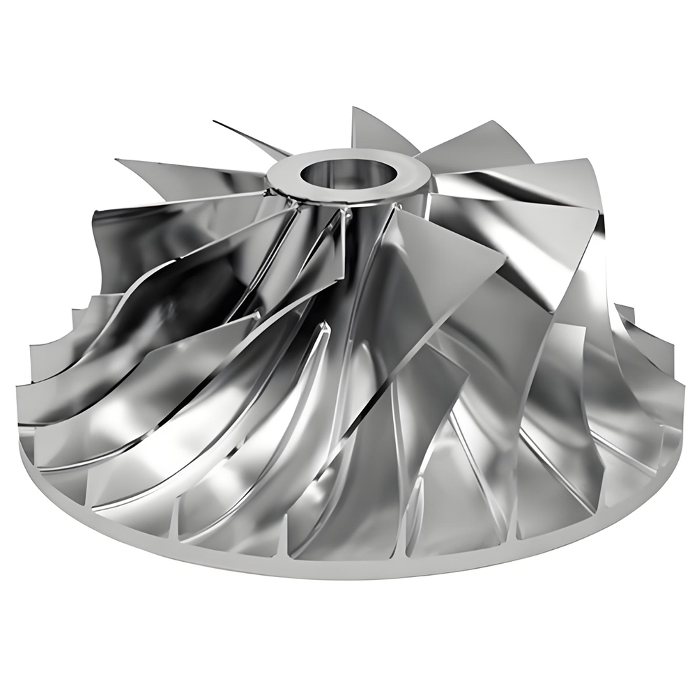
The manufacturing of closed three‑dimensional flow centrifugal impellers constitutes a core technological barrier. Due to the high blade twist, narrow passages, and large curvatures of the disk and shroud surfaces, machining is extremely difficult. Current mainstream manufacturing methods include the following five categories:
Process | Principle | Typical Application | Material Utilisation | Accuracy |
Five‑axis integral milling | Machining blades and passages from a solid forging through multiple operations | High‑performance compressors, aerospace | Low (10%) | Very high |
EDM | Using shaped electrodes to erode material by electrical discharge | Narrow passages, difficult‑to‑machine materials | Low | High |
Investment casting | Lost‑wax casting of complex shapes | Small‑to‑medium impeller batch production | High | Medium |
Segmented welding | Blades milled separately and welded to disk and shroud | Large impellers, wide passages | Medium | Medium‑high |
Additive manufacturing (3D printing) | SLM/EBM layer‑by‑layer melting of metal powder | Prototyping, ultra‑complex structures | High (95%) | Medium‑high |
Process Selection Logic
Impeller type (open/semi‑open/closed), passage width, material properties, production volume, accuracy requirements, and cost budget jointly determine the process route. In practice, combined processes (e.g., five‑axis rough milling + EDM finishing) are often used to balance efficiency and precision.
Five‑axis simultaneous CNC integral milling is currently the most mainstream manufacturing method for high‑performance closed three‑dimensional flow impellers. Starting from a solid forging, this method integrally mills blades and passages through operations including drilling, roughing, semi‑finishing, clean‑up, and finishing, all from a single blank.
Material preparation
Rough turning pre‑forming (lathe / 3‑4 axis mill removes most stock)
Drilling (drilling starting holes for passage machining)
Passage roughing (large‑diameter tools for high material removal rate)
Semi‑finishing (leaving small allowance to approach final surface)
Clean‑up (machining fillets at blade roots)
Finishing (tapered ball‑end mills for blade surfaces)
Post‑processing (deburring, polishing, dynamic balancing)
Side Milling
Uses the tool flank to machine blade surfaces in one pass. High efficiency and good surface finish, especially suitable for ruled‑surface impellers. Requires precise control of tool axis vector to avoid interference.
Point Milling
Uses the ball‑nose tip to machine curved surfaces point‑by‑point. Offers higher flexibility for complex free‑form surfaces, but slower. Scallop height can be controlled within 0.005 mm.
Trochoidal Milling
Maintains constant tool load during roughing of tough materials; arc entry reduces cutting force impact and extends tool life.
Machining Stage | Tool Type | Characteristics |
Roughing | Cylindrical / tapered milling cutters (coated carbide) | Large diameter, high material removal rate; diameter must be less than minimum blade spacing |
Blade finishing | Tapered ball‑end long‑reach cutters | Diameter 3–6 mm, cutting edge length 30+ mm for deep grooves; uses side edge for efficiency |
Passage finishing | Ball‑end / toroidal end mills | Constant scallop toolpath planning, scallop height 0.005–0.02 mm |
Clean‑up | Small‑diameter ball‑end tools | Machining fillets at blade‑hub junctions |
The core difficulties of five‑axis machining lie in tool axis vector planning and interference checking. Typical methods include:
Relative to Drive: selecting blade surfaces as drive geometry, adjacent blades and passage surfaces as check geometry, with proper lead and tilt angles.
Guide curve method: deriving tool axis guide curves by finding midpoints between boundary lines of adjacent blades and offsetting.
Constant scallop finishing: calculating stepover based on specified scallop height to generate uniform scallop toolpaths.
Helical ramping for vibration reduction: thin‑layer helical multiple ramping (pitch 0.04–0.06 mm) when tool contacts blank to avoid impact vibration.
Vibration‑Damping Tool Holder Technology
Latest patented technology employs a vibration‑damping tool holder with an internal damping core and damping oil, generating counter‑vibration to absorb holder bending deflection, significantly increasing dynamic stiffness. Combined with internal coolant supply, machining becomes more stable.
After toolpath generation, repeated verification is mandatory using simulation software.
UG NX simulation module: checks toolpath interference and overcut.
VERICUT: machine tool motion simulation, verifies CNC code, detects collisions.
Trial cutting: actual test on machine to fine‑tune cutting parameters.
EDM machining of closed three‑dimensional flow impellers adopts a digital process route with zoned, multi‑electrode, multi‑step operations:
Pre‑machining: electrodes machine passage entry.
Exit roughing: electrodes open passage exit.
Entry roughing: electrodes complete entry rough forming.
Semi‑finishing: semi‑finish electrodes with discharge gap allowance.
Finishing: electrodes achieve final accuracy.
Orbital EDM: appropriate orbital motion improves discharge gap and surface quality.
Allowance distribution: semi‑finish electrode thickened by 0.5 mm, finish electrode by an additional 0.2 mm.
Digital simulation: dynamic assembly of electrodes and fixtures on CAD platform, simulating the machining process.
Combined Five‑Axis Milling + EDM Process
For closed three‑dimensional integral impellers – with many blades, highly twisted passages, and made of difficult‑to‑cut materials – the combined process of five‑axis CNC roughing + EDM finishing is commonly used. Through UG NX analysis, passage machining zones are rationally divided, electrode design and fixtures optimised, interference simulated, and the optimal path for electrode entry/exit found.
EDM Advantages and Limitations
Aspect | Advantage | Limitation |
Capability | Machines extremely narrow passages (<10 mm), high‑hardness materials, complex spatial structures | Slow speed; each passage machined individually |
Accuracy | Separate electrodes yield simple paths and controllable accuracy | Discharge gap affects dimensional accuracy, requires multiple electrodes for compensation |
Surface quality | No mechanical stress, suitable for thin twisted blades | Recast layer requires subsequent polishing |
Cost | Can machine difficult‑to‑cut materials | High electrode manufacturing cost; significant graphite/copper consumption |
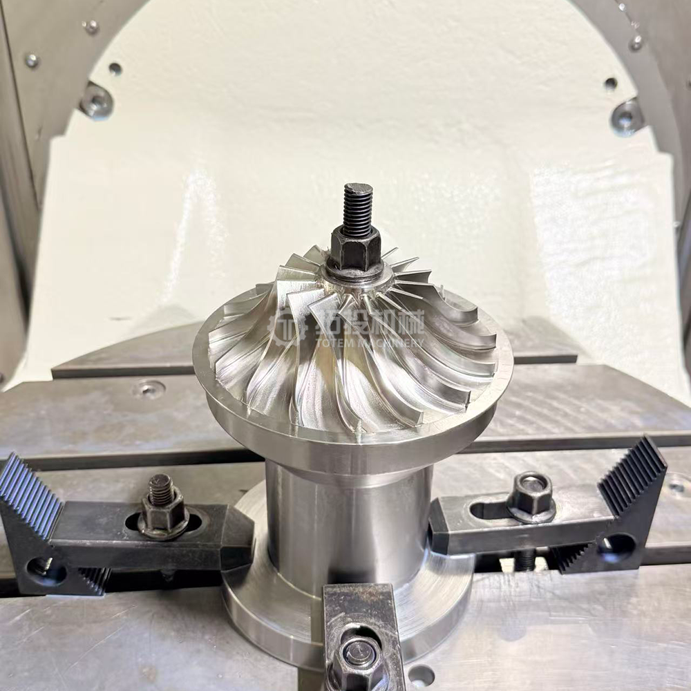
Metal additive manufacturing – particularly Selective Laser Melting (SLM) and Electron Beam Melting (EBM) – is opening an entirely new route for manufacturing closed three‑dimensional flow impellers. It breaks through the fundamental geometric limitations of traditional processes.
Ultra‑Thin Wall Forming
Achieved stable defect‑free forming of ultra‑thin blades down to 0.3 mm with yield ≥95%. In contrast, the minimum stable wall thickness for five‑axis milling in mass production is typically above 1.5 mm.
Integrated Forming
Flanges, hub, and blades are printed in one step without welding or joining. Density ≥99.9%, reaching forged material properties; fatigue life improved by over 40%.
Rapid Iteration
Lead time from design to finished part compressed from weeks to days; direct cost for small‑batch customisation reduced by over 60%. No tooling required, ideal for prototyping.
Topology Optimisation
Enables internal shaped cooling channels, double‑walled hollow structures, etc., impossible with conventional processes. Topology optimisation reduced weight by 8.7% while increasing safety margin.
Material | Application | Properties after SLM |
Inconel 718 nickel‑based superalloy | Long‑term service at 650°C | Density ≥99.95%, tensile strength >1200 MPa |
Ti‑6Al‑4V titanium alloy | Very high tip speeds, moderate temperatures | High strength‑to‑weight ratio, corrosion resistant |
New aluminium alloys | High‑temperature parts up to 400°C | Strength 5× that of conventional cast aluminium |
Stainless steels (316L / 17‑4PH) | Corrosive environments | Good corrosion resistance and mechanical properties |
Support removal – cut off support structures.
Stress relief – heat treatment to eliminate residual stress.
Hot Isostatic Pressing (HIP) – achieves 99.9%+ density.
Surface finishing – machining / polishing / abrasive flow machining.
Final machining – precision finishing of critical surfaces + dynamic balancing.
Current Limitations
Residual stress in metal 3D‑printed parts can cause distortion, requiring additional heat treatment correction.
High‑performance printing materials are costly, limiting mass production.
Non‑destructive testing for internal defects in complex structures is still immature.
Printed surface roughness (Ra 6–15 μm) necessitates subsequent machining of critical surfaces.
Investment casting is widely used for medium‑batch production of complex‑geometry or difficult‑to‑machine impellers, especially in industrial compressors and some gas turbines.
Process: produce precise wax pattern → repeatedly dip into ceramic slurry to build shell → dewax → vacuum/pressure pour molten metal → shell removal → Hot Isostatic Pressing (HIP) to eliminate micro‑porosity → machine critical surfaces → dynamic balancing.
Advantages: can produce highly complex shapes (blades as thin as 0.7–2.0 mm), minimal material waste, suitable for batch production, applicable to superalloys.
Limitations: high initial tooling cost, possible casting defects (porosity, inclusions), strength and surface finish generally lower than machined parts.
Rapid casting: uses FDM 3D‑printed wax patterns to reduce prototype/small‑batch cost and lead time.
For large industrial compressor impellers or impellers with wide outlet passages, segmented welding remains an important method. Depending on passage width, there are two main approaches:
Wide‑Passage Welded Impeller
Blades separately pressed or milled, then welded to disk and shroud.
Manual arc welding or TIG welding, performed internally or externally.
Preheating at 250–360°C, post‑weld heating at 650°C for 3 h to relieve stress.
Narrow‑Passage Slot‑Welded Impeller
When outlet width <10 mm, electrodes cannot reach into the passage.
Slots are milled in the disk and blades are milled on the shroud, then assembled and welded.
Requires precise determination of initial slot angle on disk to ensure profile matching.
Electron Beam Welding
High‑quality, deep penetration, minimal distortion.
Suitable for closed impeller shroud welding.
Requires full NDT after welding (radiography, penetrant inspection).
Electrochemical Machining (ECM)
Used for finishing hardened materials or machining thin twisted blades without mechanical stress. No tool wear, no residual stress.
Abrasive Waterjet
Used for rough profiling of 2D blades in open impellers or cutting basic contours from thick plates.
Hybrid Manufacturing
Additive manufacturing (building near‑net shape) + subtractive CNC machining (finishing critical surfaces) on the same machine, combining both advantages.
Powder Metallurgy – Hot Pressing
Integral forming followed by high‑temperature solution treatment, high‑temperature tempering, and PVD coating, reducing welding/machining defects and improving wear and corrosion resistance.
Closed three‑dimensional flow centrifugal impeller machining is widely recognised as one of the most complex tasks in precision manufacturing. Its core challenges stem from the triple combination of geometric complexity, material difficulty, and accuracy requirements.
Challenge | Specific Manifestation | Countermeasures |
3D twisted blades | Irregular curved surfaces with large twist, non‑uniform B‑spline surfaces | Five‑axis side milling, precise tool axis vector control |
Narrow passages | Outlet width may <10 mm, severely limited tool space | Small‑diameter tapered ball‑end tools + EDM combined process |
Main and splitter blades | Interleaved structure makes passages more twisted and cramped | Zoned multi‑electrode EDM, separate electrode design |
Thin leading/trailing edges | Extremely thin edges prone to chatter and deformation | Thin‑layer cutting, vibration‑damping holders, optimised parameters |
Titanium Alloys (Ti‑6Al‑4V)
High strength‑to‑weight ratio, but low thermal conductivity (heat concentrated at the cutting edge) and work hardening tendency. Requires low cutting speeds, high feed rates, and ample cooling.
Nickel‑Based Superalloys (Inconel 718)
Preferred for high‑temperature applications but extremely demanding on cutting tools. Severe work hardening and rapid tool wear. Often requires EDM assistance.
High‑Strength Stainless Steels (17‑4PH)
Used in corrosive environments. High strength and toughness result in high cutting forces, requiring rigid machine tools and fixtures.
Interference and Collision: Tool movement inside twisted blade passages readily causes interference with adjacent blades or passage surfaces. Comprehensive interference checking and simulation verification in CAM software are essential.
Machining Deformation: Thin blades elastically deform under cutting forces, causing spring‑back errors after machining. Compensation surfaces based on blade deflection must be established.
Tool Overhang: Deep groove machining requires long‑reach tools with poor rigidity and vibration susceptibility. Vibration‑damping holders and helical ramping strategies are employed.
Surface Quality: Aerodynamic performance depends on accurate blade contours and smooth surfaces (Ra < 0.8 μm). Tool mark direction and size directly affect flow losses.
Thermal Deformation: Cutting heat raises workpiece temperature, causing distortion. Adequate cooling and thermal compensation are necessary.
Coupled Analysis of Interference and Deformation
Recent research couples tool interference errors and blade deformation errors in five‑axis machining. By establishing a blade deformation compensation surface and pre‑compensating in toolpath planning while simultaneously controlling interference errors, "collision‑free, minimal‑error" high‑efficiency precision machining is achieved. Measured machining errors can be controlled within tolerance.
During machining, cutting forces from the outlet inward are complex, often causing instability. Dedicated fixture design must:
Enable pre‑alignment outside the machine using pull studs, locating rings, orientation rings, and clamping rings for positioning and clamping.
Provide rapid positioning, high accuracy, and high repeat positioning accuracy.
Accommodate clamping needs for different machining operations.
Minimise clamping setups – complete as much machining as possible in one setup.
Surface quality directly affects impeller aerodynamic efficiency, fatigue life, and corrosion resistance. Surface treatment of closed three‑dimensional flow impellers is an integrated system of multiple processes.
Polishing narrow‑passage closed impellers is a global challenge. Traditional grinding cannot reach many internal passage areas. Effective polishing methods include:
Method | Principle | Achievable Roughness | Applicable Area |
Wet blasting + shot peening | Overall pre‑treatment, removes scale and large particles | Ra 3–6 μm | Entire impeller |
Ultrasonic vibration polishing | Ultrasonic‑frequency vibration drives abrasive cutting | Ra 0.4 μm | External surfaces |
Abrasive flow machining | Viscous elastic media with abrasives flows through passages under pressure | Ra 0.2 μm | Internal passages |
Hydraulic grinding | High‑speed flow of quartz sand + water mixture through passages | Ra 0.8 μm | Narrow internal passages |
Best Practice Combination
Research by Shenyang Blower Works and Dalian University of Technology shows that the combination of wet blasting + shot peening → external ultrasonic vibration polishing → internal abrasive flow polishing yields optimal results, achieving final surface roughness Ra 0.2 μm, meeting the surface requirements of high‑pressure low‑flow centrifugal compressors. Hydraulic grinding can improve pump efficiency by 3%–6%.
PVD Physical Vapour Deposition
EB evaporation mode, 400°C process temperature, 6 hours. TiC‑Al₂O₃ composite nano‑coating, 2 μm thick, improves wear resistance and flow passage smoothness.
Electroplating / Electroless Plating
For impellers operating in corrosive environments, nickel or chromium coatings provide corrosion protection.
Thermal Spraying
Plasma spraying of ceramic or alloy coatings for high‑temperature environments, imparting high‑temperature resistance, wear resistance, and oxidation resistance. Tungsten carbide coatings can extend impeller life to 3–5 years.
Impeller inspection spans the entire manufacturing process – from raw material to finished product – with standards and methods comparable to aerospace components. A complete inspection system covers the following six dimensions:
Equipment | Accuracy | Inspection Content |
CMM | Spatial accuracy 1.8 + L/350 μm | Full dimensional measurement of blade profile, contour, thickness, position, angles, etc. |
Blue light scanner (non‑contact) | Point accuracy ±15 μm | Rapid acquisition of complete surface point cloud data |
Structured light binocular grating | Micron‑level | Non‑contact 3D topography measurement, comparison with design model |
White light interferometer | Resolution 0.1 μm | Surface topography measurement, subsurface defect identification |
At high rotational speeds (8,000–20,000 r/min), even minor mass imbalance generates huge centrifugal forces causing severe vibration.
Standard: ISO 21940‑11 / ISO 1940‑1, balance quality grade G2.5.
Equipment: high‑precision dynamic balancing machine, minimum achievable residual unbalance ≤0.1 g·mm/kg.
Method: two‑plane balancing, correction by material removal (drilling) or addition.
Requirement: residual unbalance within 5 g·mm/kg.
Ultrasonic Testing (UT): detects internal porosity, inclusions, laminations. Sensitivity: 2 mm flat‑bottom hole. Suitable for casting/forging blanks and finished parts.
Radiographic Testing (RT): real‑time X‑ray imaging checks internal structural integrity. Conforms to ASME BPVC. Finds internal defects invisible to the eye.
Magnetic Particle Inspection (MT): detects surface and near‑surface cracks in ferromagnetic materials. Can find micro‑cracks >0.5 mm.
Penetrant Testing (PT): detects surface‑breaking cracks in non‑magnetic materials. Fluorescent or colour contrast, suitable for stainless steel and titanium alloy impellers.
Eddy Current Testing (ET): rapid screening of near‑surface defects, suitable for online inspection of mass‑produced impellers.
Chemical composition: spark OES / XRF / ICP‑OES for precise quantification.
Mechanical properties: universal testing machine – tensile strength ≥500 MPa, yield strength, elongation; impact testing (‑40°C low‑temperature).
Metallography: microscope observation of grain size, inclusion rating (ASTM E112), to avoid heat‑treatment defects.
Hardness: Rockwell / Brinell hardness tester.
Hydraulic / aerodynamic testing: on test rig, measure flow‑head curve, ensure efficiency ≥85%, NPSH meets requirements.
High‑speed spin test: rotation test rig up to 300 m/s peripheral speed, replicating actual conditions.
Environmental simulation: temperature chamber (‑70°C to 300°C) and vacuum chamber (≤10⁻⊃3; Pa), salt spray corrosion chamber (ASTM B117).
Fatigue testing: high‑cycle fatigue machine, cycle count ≥10⁷.
Inspection Environment Requirements
Temperature maintained at 20±2°C, humidity <60% to reduce measurement errors. Inspectors must hold ASNT Level II or equivalent certification. MES system records all inspection data for full lifecycle traceability.
2024 data show strong demand for three‑dimensional flow impeller technology in power, metallurgy, chemical, and other industries. Energy‑saving three‑dimensional flow centrifugal blowers generated approximately 3,000 units of new demand in data centre cooling systems (market size RMB 1.8 billion, annual growth 65%), 2,200 units in the new energy vehicle manufacturing supply chain, and 500 units in the semiconductor manufacturing industry (RMB 1.5 billion, growth 35%). Major industry players allocate 6.8% of sales revenue to R&D. Centrifugal blowers employing three‑dimensional flow design achieve 12%–18% energy savings compared with traditional two‑dimensional designs.
Digital Intelligent Manufacturing
Predictive maintenance based on digital twins aims to reduce unplanned downtime by 50%. Combining CFD simulation with experimental validation shortens new product development cycles by 30%. MES systems enable full lifecycle data traceability.
Scaling of Additive Manufacturing
SLM/EBM technology is moving toward mass production. Ultra‑thin 0.3 mm blade forming has been achieved, with topology optimisation reducing weight by 8.7%. Hybrid manufacturing (additive + subtractive integrated) will become a new paradigm for high‑end impeller production.
High‑Speed Direct Drive Integration
High‑speed permanent magnet synchronous motors directly drive impellers, with motor efficiency ≥95%, eliminating gearbox losses. Integrated gear‑impeller units are becoming a trend, enabling wide flow‑pressure regulation via variable frequency drive.
Full‑System Co‑Optimisation
Impeller design is optimised simultaneously with diffusers, volutes, and motors, using CFD to maximise overall compressor system performance. Shifting from component‑level to system‑level integrated optimisation.
IoT (Internet of Things) Intelligent Monitoring
In 2024, 39% of newly installed units are smart fans equipped with remote monitoring. Big‑data analysis enables dynamic energy optimisation, achieving an additional 3%–5% average energy saving. By 2025, smart fan connectivity is expected to exceed 60%.
New Materials and New Structures
Materials Genome Engineering screens novel alloy formulations with strength five times that of conventional cast aluminium. Innovative designs such as composite impellers, double‑walled hollow structures, and internal cooling channels continue to emerge. High‑temperature composite impellers resistant to 400°C+ are under development.
From cast aluminium to 3D‑printed titanium alloy blades, from two‑dimensional to three‑dimensional flow, from segmented welding to integral milling – the manufacturing technology of closed three‑dimensional flow centrifugal impellers is undergoing profound transformation. The convergence of additive manufacturing, digital twins, and AI‑driven design optimisation will continue to improve impeller efficiency, capacity, and reliability, providing core support for industrial energy conservation and the self‑reliance of high‑end equipment.


