


| Quantity: | |
|---|---|
The fine toothed roller is the core working component of twin-roll crusher/pulverizing equipment, specifically designed for medium and fine crushing of food materials. Through the shearing and squeezing action generated by the counter-rotation of two rollers, it breaks down large pieces of material to the required particle size. It is widely used in the primary and fine crushing processes of food raw materials such as cocoa beans, soybeans, nuts, and cereals.
Unlike rollers used in coarse crushing equipment, the fine toothed roller features precision tooth profiles and uniform output as its core competitive advantages, ensuring crushing efficiency while maintaining material integrity and food hygiene and safety requirements.
Key Advantages:
High shearing precision with uniform output particle size
Built-in classification function to avoid over-grinding
Suitable for low-hardness, high-viscosity, and heat-sensitive food materials
The fine teeth of the toothed roller have the following advantages in structure:
Precision shearing and crushing: The teeth are densely arranged, applying high-frequency, low-amplitude shearing forces to the material, gradually breaking particles down to a fine and uniform state, achieving particle fineness at the 15–20 μm level.
Crushing while screening: The inter-tooth gaps naturally form a "sieve" effect – particles smaller than the gap pass through directly, while larger particles are captured and sheared, resulting in uniform and controllable output particle size.
Avoiding over-grinding: The fine tooth structure does not excessively compress qualified particles, effectively controlling the fine powder rate and reducing material loss.
Gentle processing: Suitable for food materials with lower hardness, avoiding "impact breakage" that produces irregular particles, thus preserving the original quality of the material.
The tooth grooves of the fine toothed roller are shallow and dense, so material does not easily accumulate or clog between teeth, and sticky materials are less likely to retain, agglomerate, or spoil. This structure also facilitates hygienic cleaning, leaving minimal residue and reducing bacterial growth.
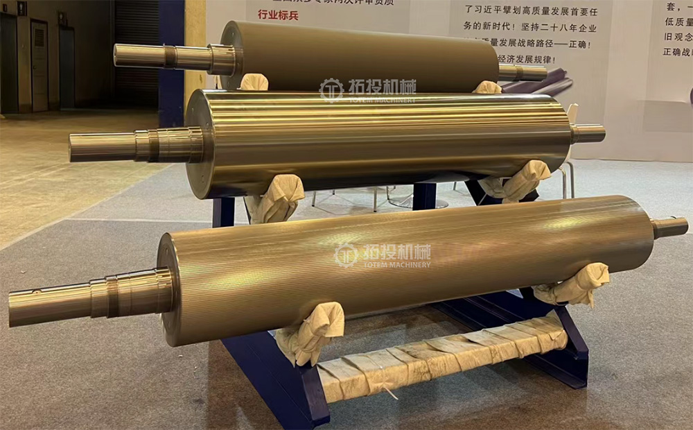
The high-chromium nickel‑molybdenum alloy offers excellent hardenability and outstanding wear resistance. After heat treatment, the tooth surface hardness can reach 50–65 HRC.
The alloying elements provide the following characteristics: Chromium (Cr) forms high-hardness Cr₇C₃-type carbides, offering excellent resistance to abrasive wear; Nickel (Ni) improves hardenability, promotes martensitic transformation, and enhances hardness; Molybdenum (Mo) inhibits pearlite formation, improves hardenability, and refines carbides.
Leveraging the advantages of material and structure, this toothed roller is specialized for food crushing and screening:
Cocoa bean crushing: Breaking whole cocoa beans into small pieces in preparation for subsequent refining.
Soybean/legume pulverization: Medium and fine crushing of beans.
Nut crushing: Shelling or breaking of peanuts, almonds, and other nuts.
Grain processing: Crushing of corn, wheat, and other cereal crops.
Food additives/spices: Pulverization of spices and seasonings.
High-quality high-chromium nickel-molybdenum alloy forged round steel is selected, heated to high temperature, and repeatedly upset and drawn out using a forging press to refine the internal grain structure and achieve a dense microstructure. The forged material is cut to the design dimensions of the toothed roller, with a machining allowance of 1–2 mm reserved.
The forged blank undergoes rough turning to remove surface scale and irregular excess stock, and the main contours such as journals and roller body are preliminarily shaped, with allowance reserved for subsequent finishing operations.
After rough machining, the component is subjected to overall quenching and tempering. The roller body is heated to the quenching temperature as a whole, oil-quenched or water-quenched, and then high-temperature tempered to obtain a uniform tempered sorbite structure. This process balances the strength and toughness of the toothed roller to meet heavy-load and fatigue resistance requirements.
The tooth surface is subjected to induction hardening: high-frequency induction heating of the tooth surface followed by rapid cooling raises the tooth surface hardness to 50–65 HRC, significantly improving wear resistance.
After quenching and tempering, low-temperature tempering or natural aging is carried out to eliminate internal stresses, preventing deformation due to stress release during subsequent finishing operations and ensuring dimensional stability.
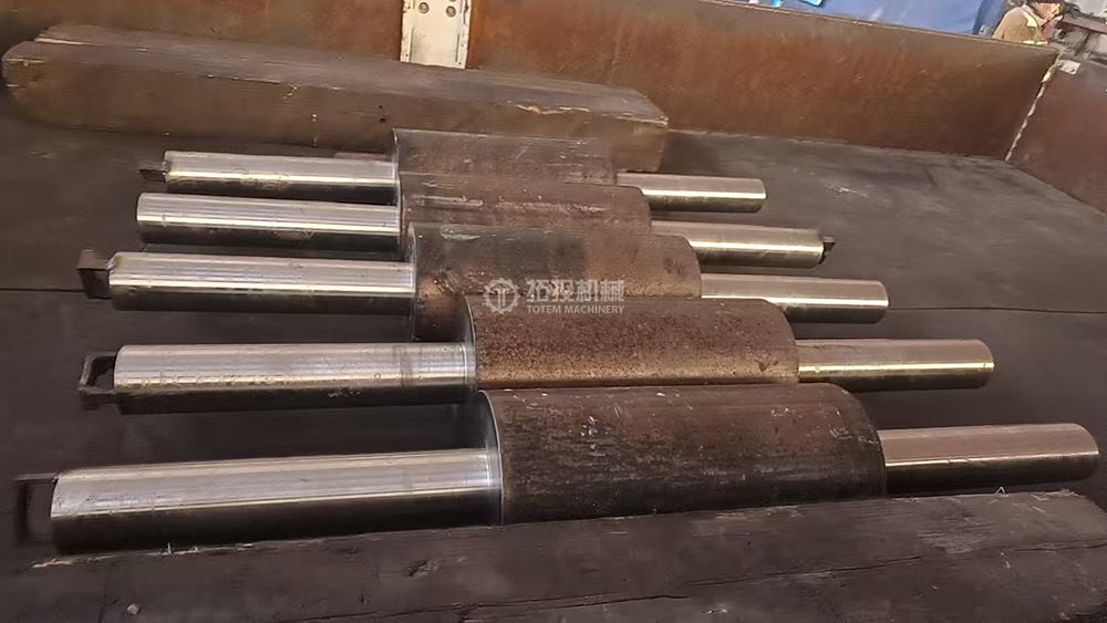
After Heat Treatment
The outer diameters, grooves, steps, and other features are re-turned, reducing the allowance to within 0.5 mm. Auxiliary structures (e.g., keyways, threads) are machined simultaneously, with strict control of coaxiality, cylindricity, and other geometric tolerances.
Turning/grinding: Critical sections such as bearing fit areas and coupling connection sections are progressively refined through precision turning → grinding to achieve the required accuracy.
Connection feature machining: Keyways are milled and threads are tapped to ensure dimensional and geometric tolerances of connecting parts.
Tooth milling: A CNC milling machine with high-hardness carbide tools is used for precision tooth profile milling, machining each tooth to the designed pitch, tooth depth, and tooth profile.
Toothed Roller Lathe Finish
Toothed Roller Gear Milling
After cleaning and drying, the entire roller surface is coated with a food‑contact grade rust preventive oil certified to NSF‑H1. This oil is based on food‑grade mineral white oil and contains no sulfur, chlorine, or heavy metal components, meeting incidental food contact safety standards. The application process ensures full coverage of precision areas such as tooth surfaces and journals, providing effective rust protection during warehousing and ocean shipping.
Transparent PE plastic film is used to completely wrap and seal the fine toothed roller, forming a moisture-proof layer. The tooth surface is additionally wrapped with white bubble wrap on the outer layer to prevent tooth tip damage during transportation.
Key functions include: isolating moisture to prevent rust; blocking dust to keep the tooth surface and grooves clean; and reducing friction and scratches between the roller and packaging material through tight film wrapping, thus preserving tooth profile accuracy.
Solid wood or plywood wooden cases are used, with coloured woven cushions or foam cushioning material inside. Critical areas such as the tooth surface and journals are additionally protected with protective sleeves or localized foam wrapping to prevent tooth tips from colliding inside the case. The wooden case frame offers compressive and impact resistance, capable of withstanding mechanical forces during stacking and handling. The cushioning layer fills gaps, absorbs vibration, and prevents deformation or tooth surface damage from jolting. The robust wooden construction is compatible with forklifts and cranes, meeting warehouse storage requirements.
Inner Packaging
Outer Packaging
Packaging procedure: First, the fine toothed roller is cleaned and dried to remove processing residues (cutting fluid, metal chips, etc.). The roller surface is coated with rust-preventive oil, then wrapped and sealed with PE film. Precision areas such as the tooth surface and journals are additionally protected with localized foam. The roller is then placed into the wooden case, secured with cushioning pads to prevent shifting during transit. Finally, the case is fastened with nails or straps, and shipping labels such as "This Side Up", "Keep Dry", "Precision Equipment", and "No Heavy Stacking" are affixed. For export, the wooden case bears a fumigation mark to meet international shipping requirements.
This entire system establishes a "from inside out" protective network that combines precision, impact resistance, and environmental adaptability, ensuring the product arrives in perfect condition.


